Chris 2Y
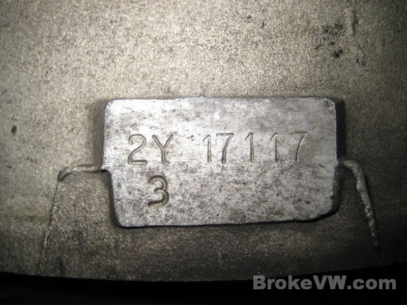
2Y17117
Arrived 11/14/12 Started 3/29/13 Done 04/26/13
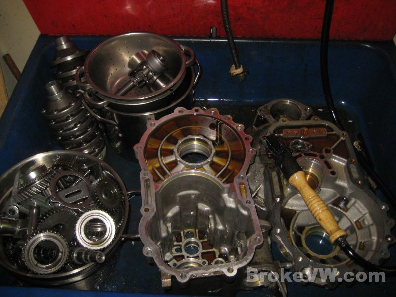
The teardown has started on your trans, it doesn't look too horrible inside. I think it will make a good candidate for a rebuild.
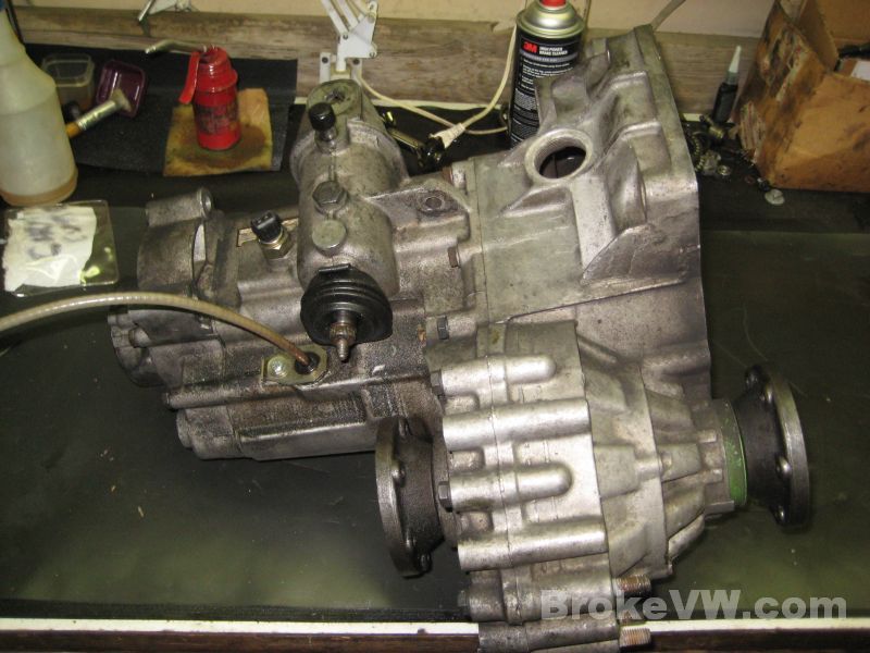
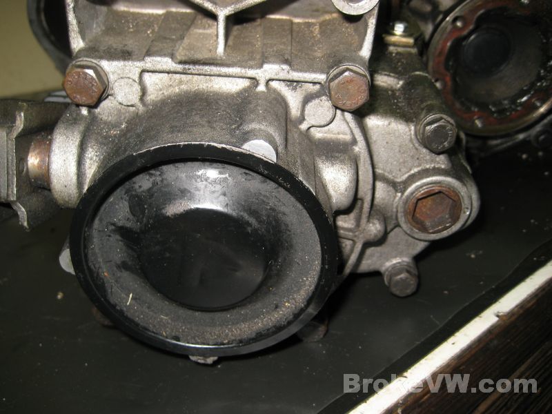
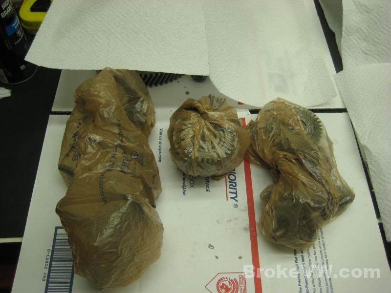
This is how the trans looked when I picked it up...
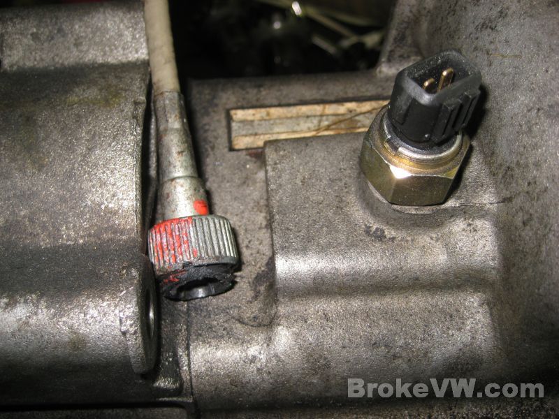
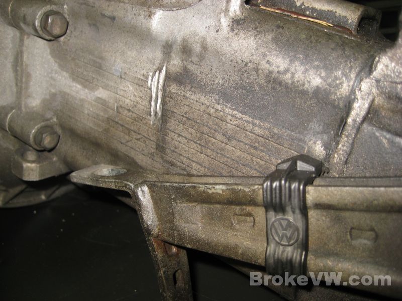
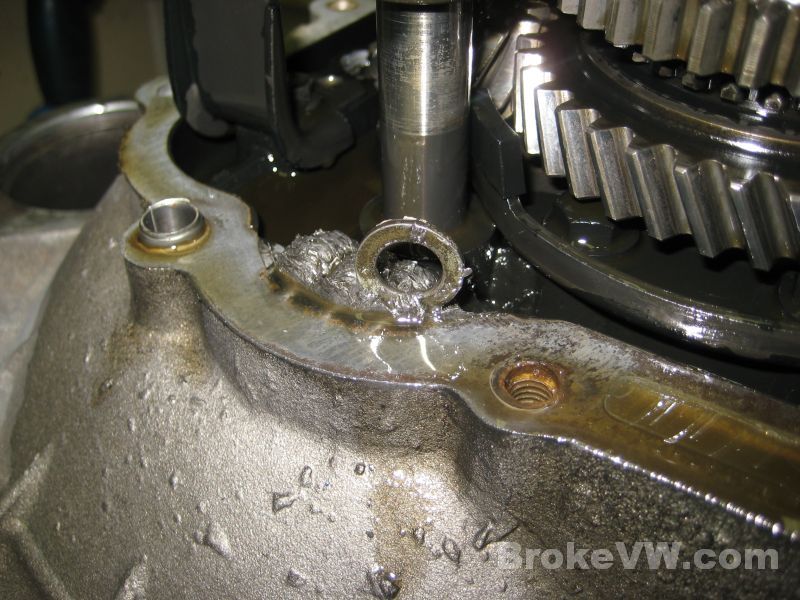
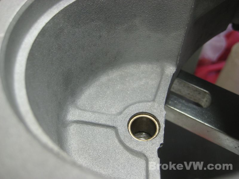
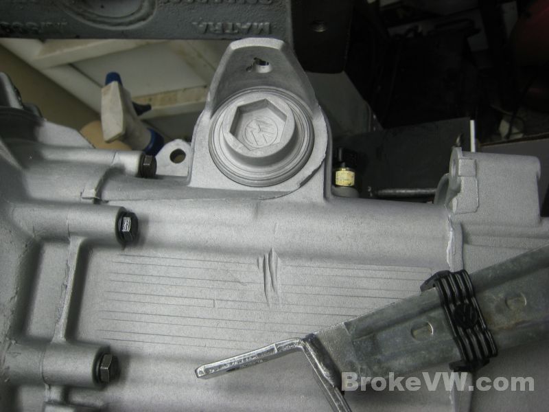
The clutch cable retaining pieces have been twisted and started cutting into the casing front, as well as into the ledge where the clutch cable sits...
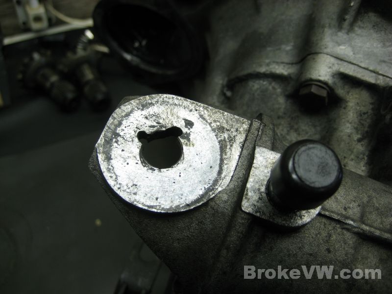
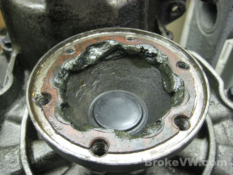
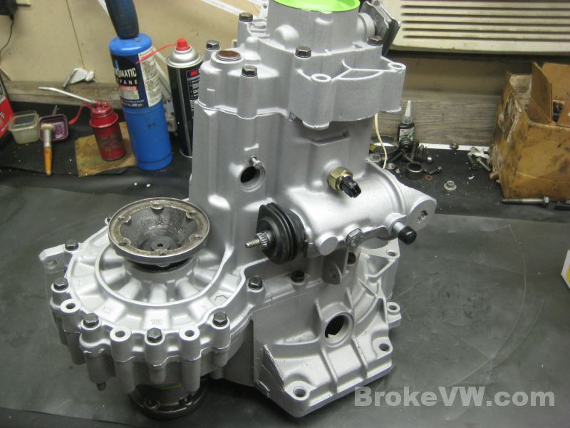
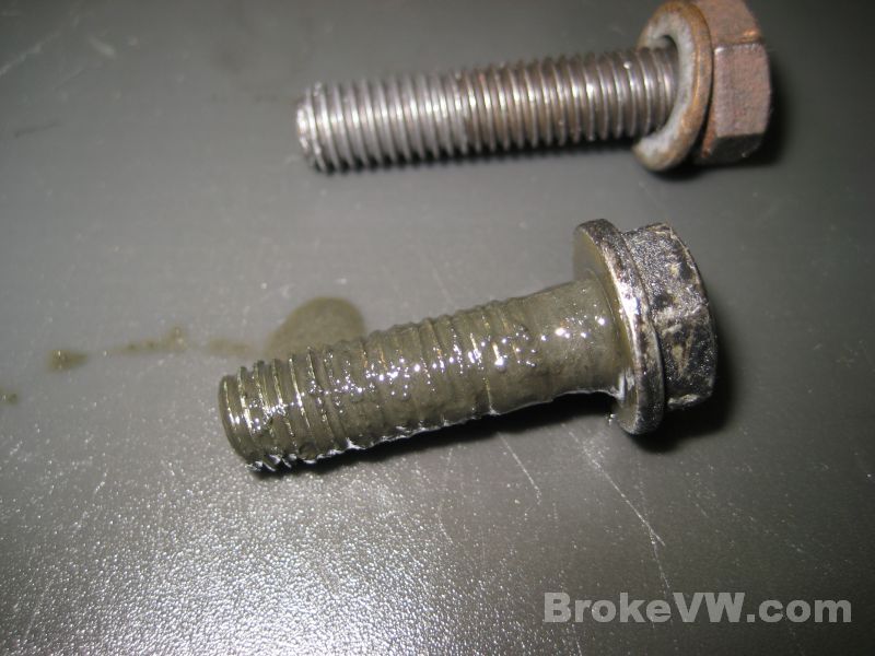
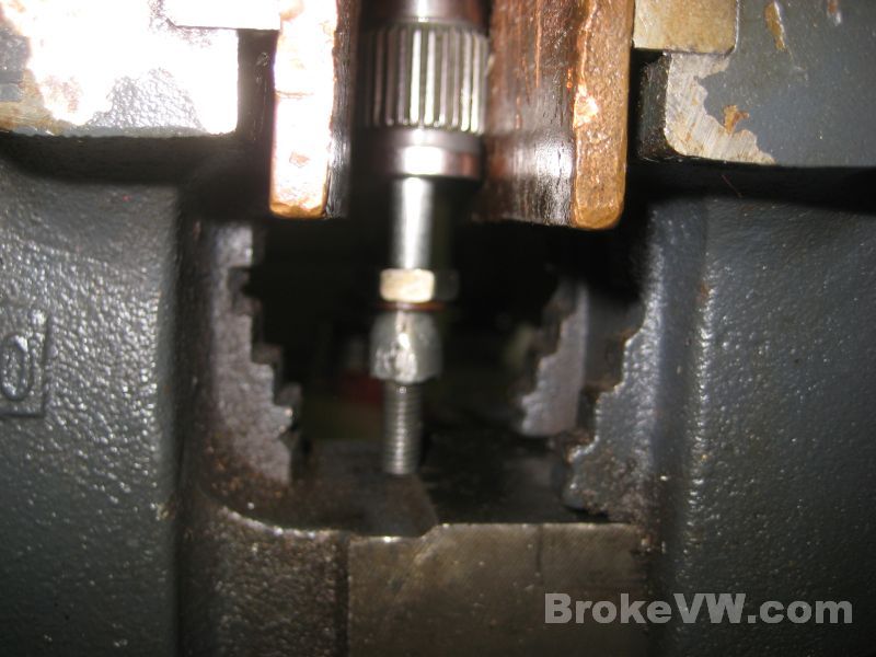
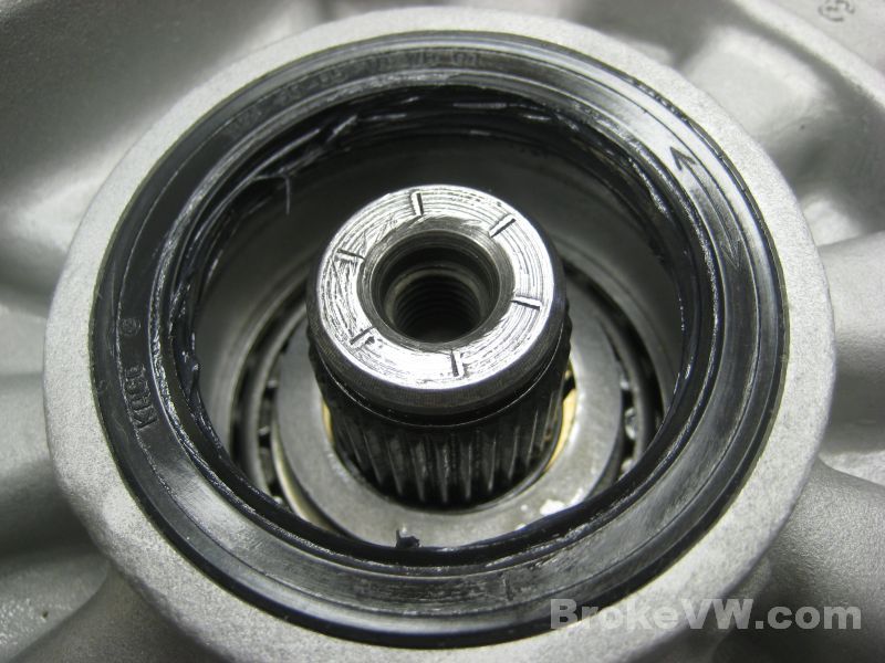
When the reverse bolt was removed, the threads were packed with gunk, so I kind of expected to see a lot of build-up of gunk inside the trans...
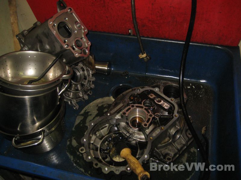
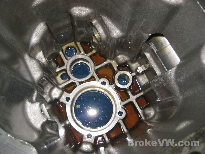
I was surprised to find the inside of the 5th housing relatively clean...
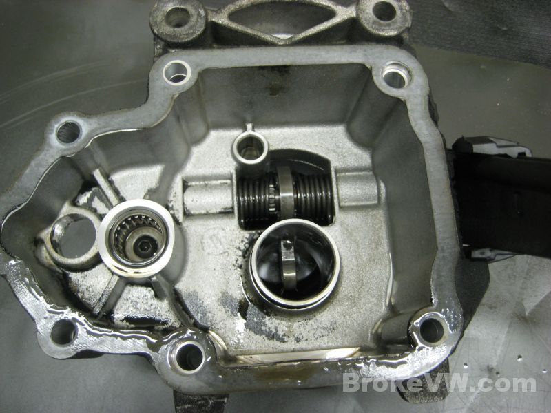
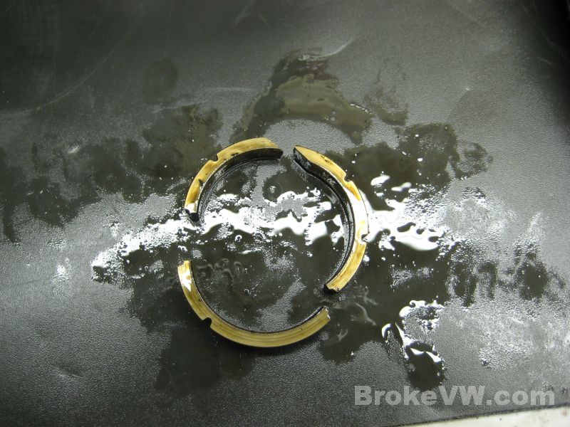
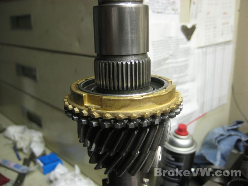
The bronze concical thrust rings in the trans are broken, this is common as these pieces are very fragile and are easily cracked.
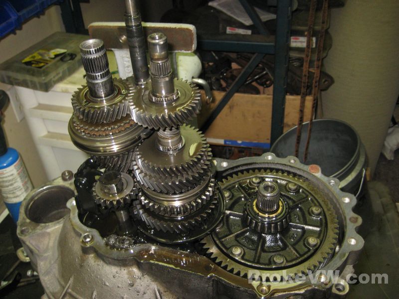
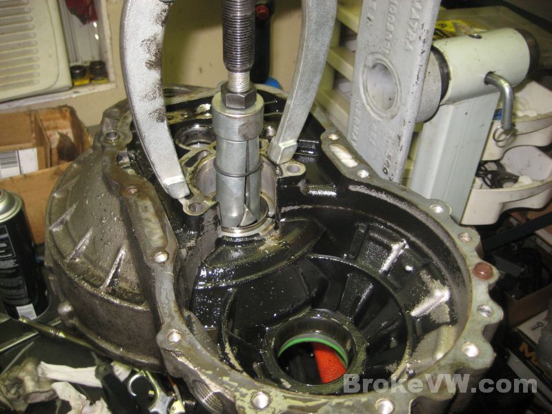
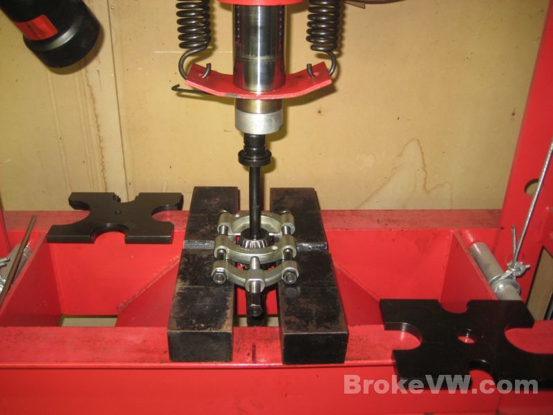
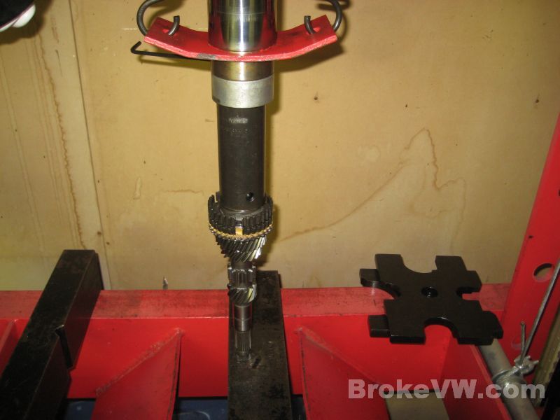
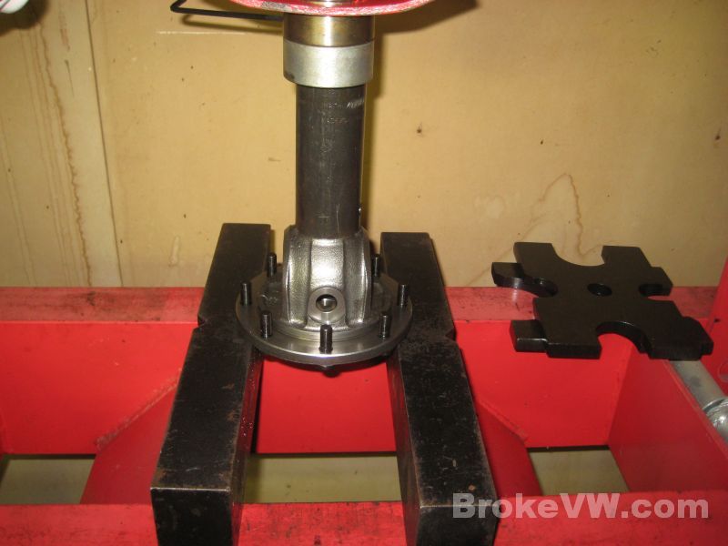
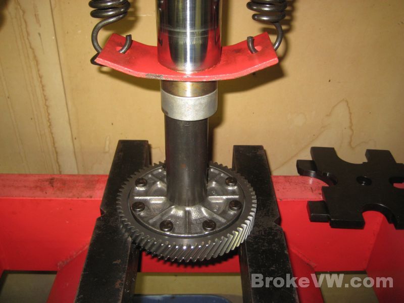
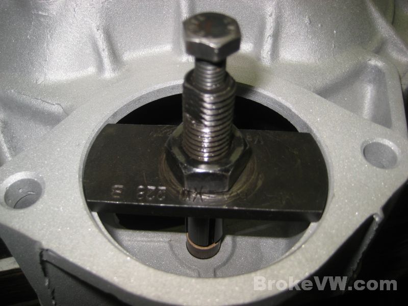
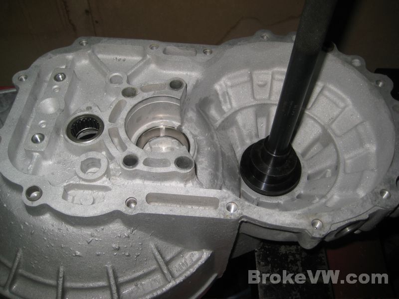
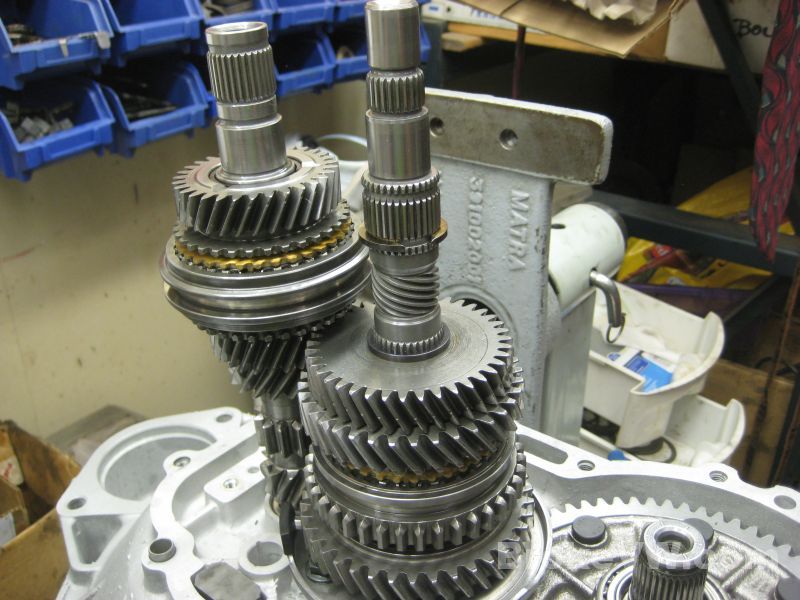
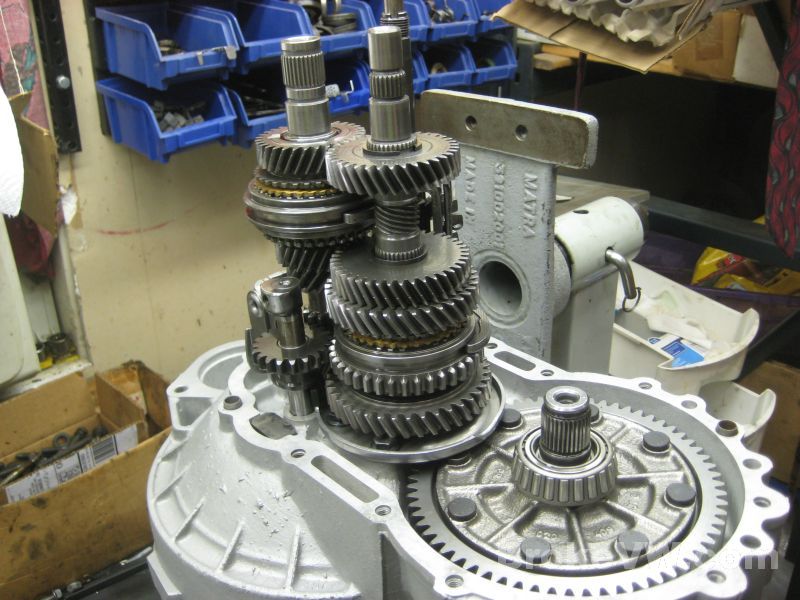
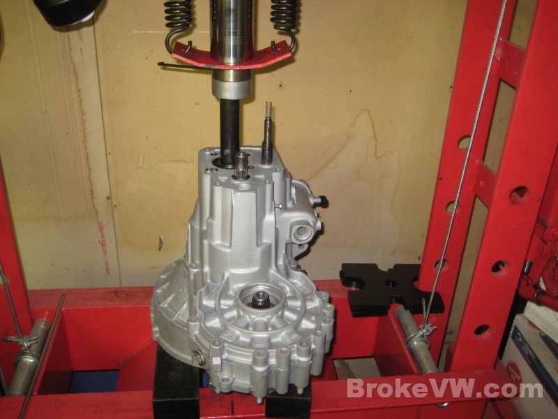
Preparing to split the trans, the input shaft is supported from below with a support bar. This keeps the press forces needed to split the trans from going anywhere but into that heavy input shaft and the bellhousing of the casing. No gears or bearings will be exposed to the forces needed to split the trans...
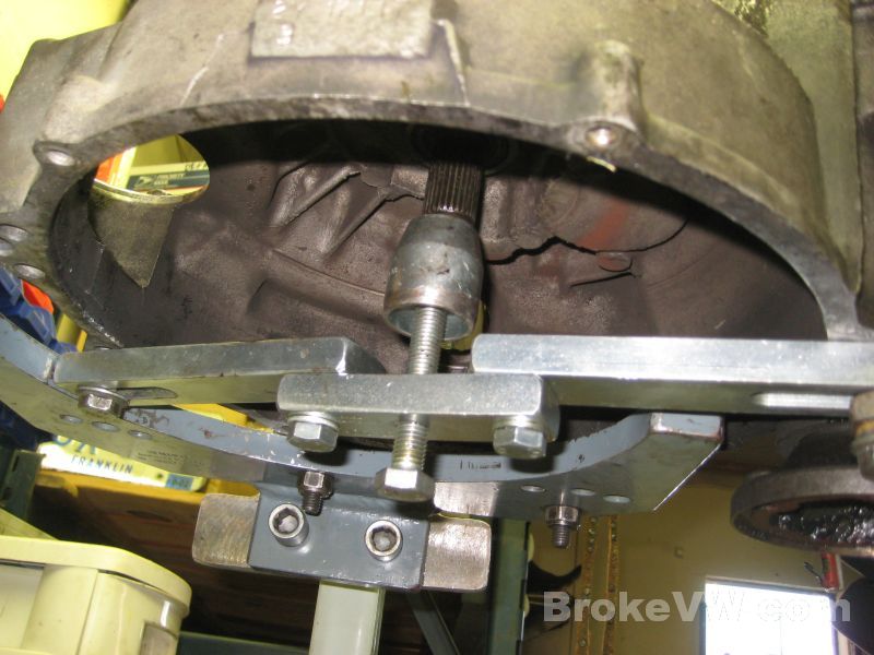
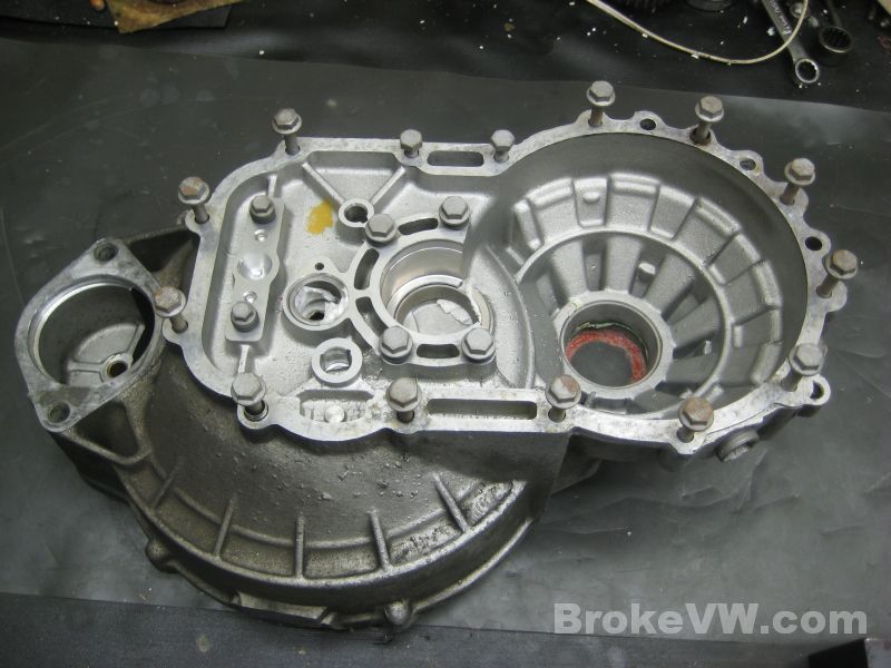
The splitter tool installed and the case partially split open...
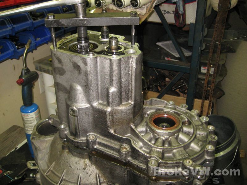
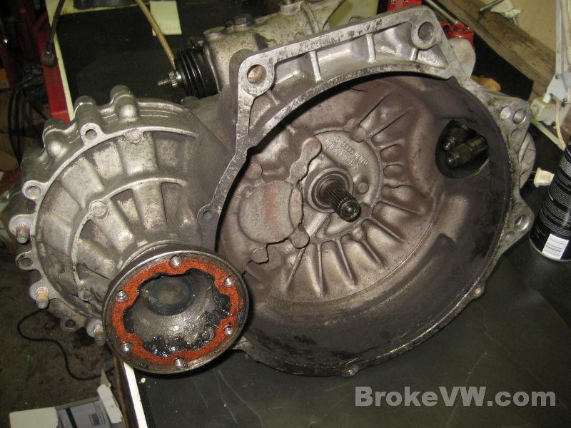
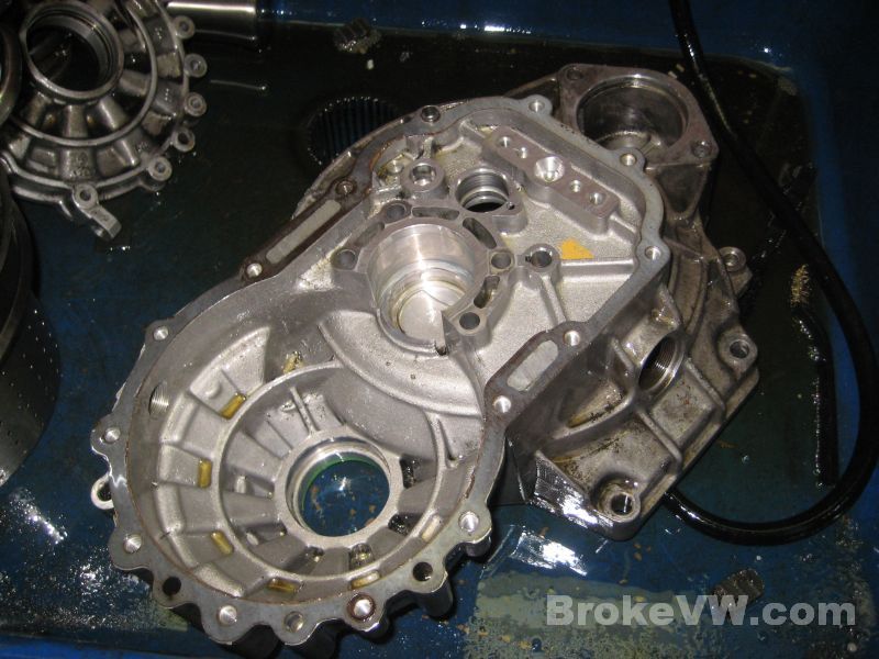
The flanges show some wear, but nothing too bad...

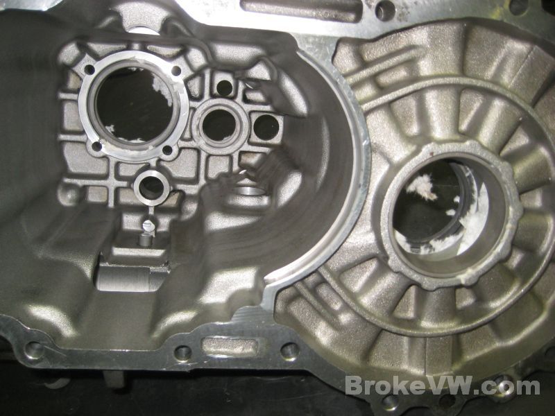
The inside has been stained with the black oil film, but it isn't thick like some trans....
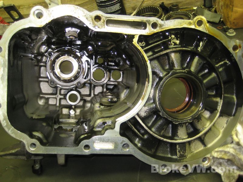
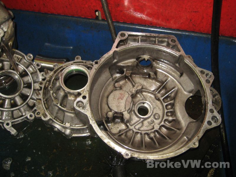
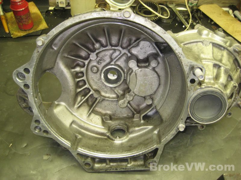
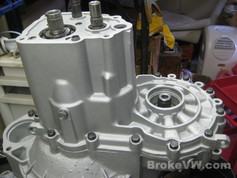
Split open....
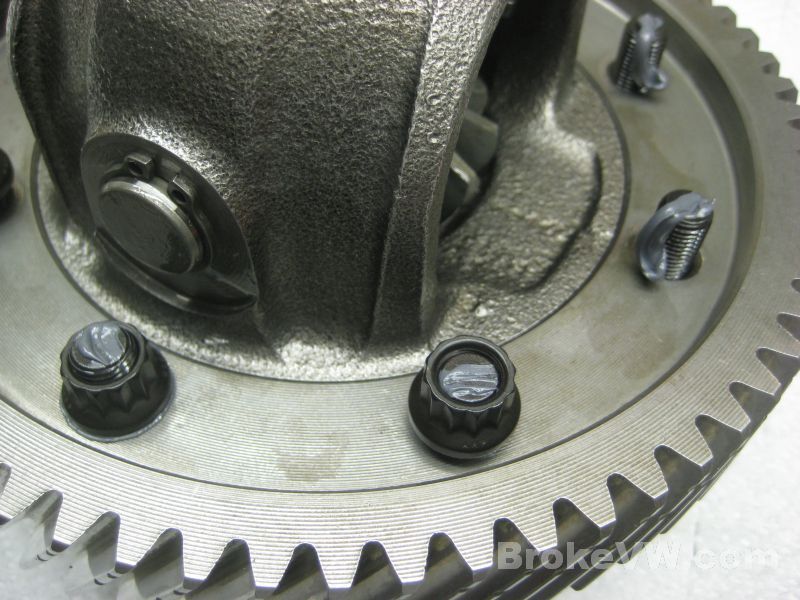
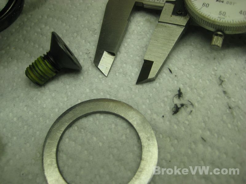
The magnet works. This little guy is a lock washer, one of those split-type like you find on the 3 studs around the diff that secures the trans mount. There are 3 M10 studs sticking out for the rear mount bracket and 3 split lock washers and 3 nuts are on those studs, this washer looks like one of those split lock washers....
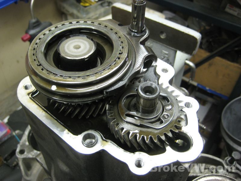
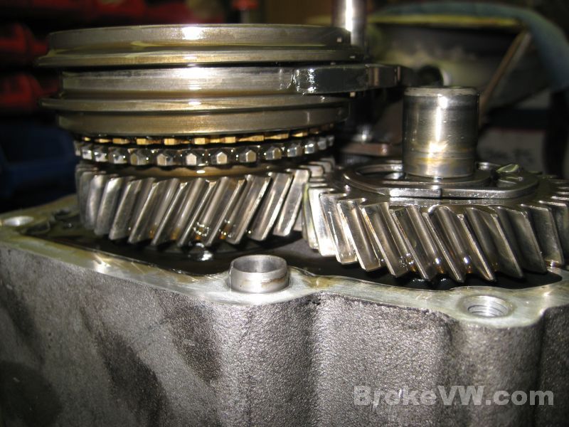
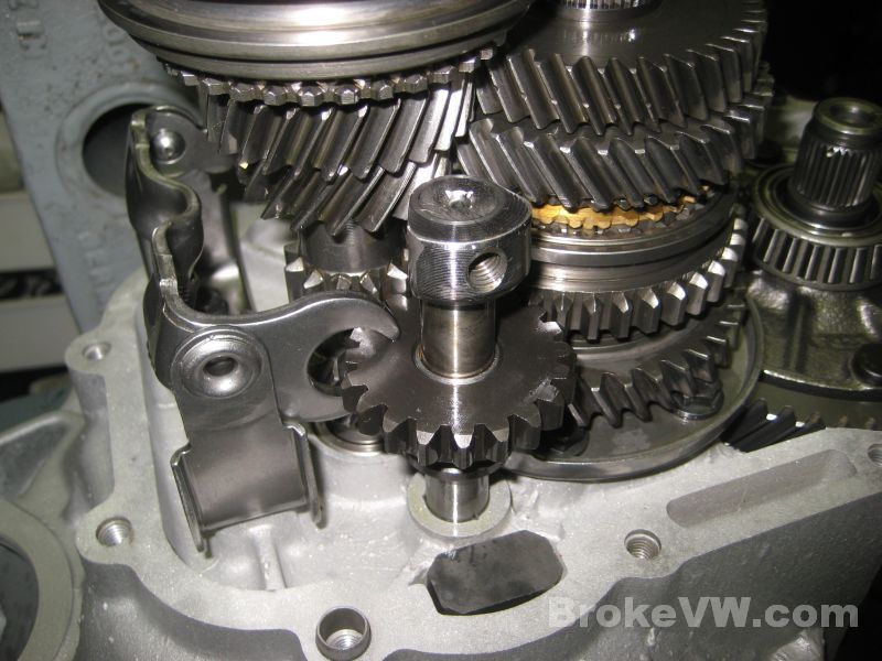
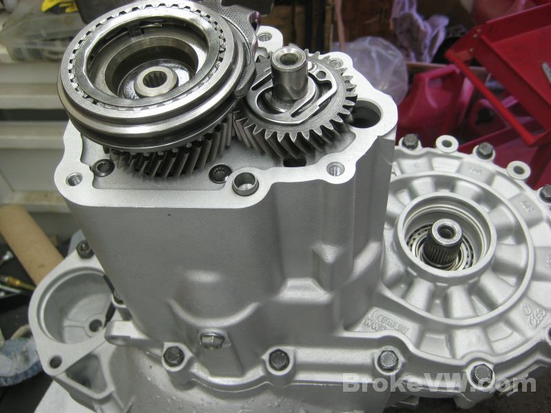
The idler gear doesn't look too bad on this side...
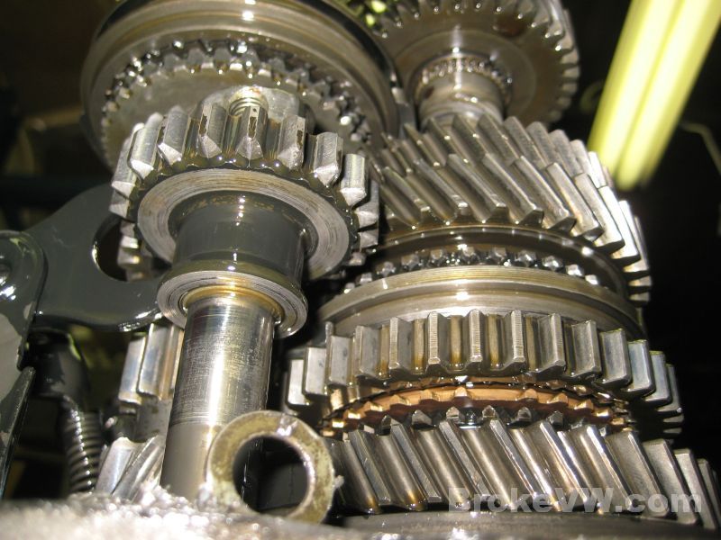
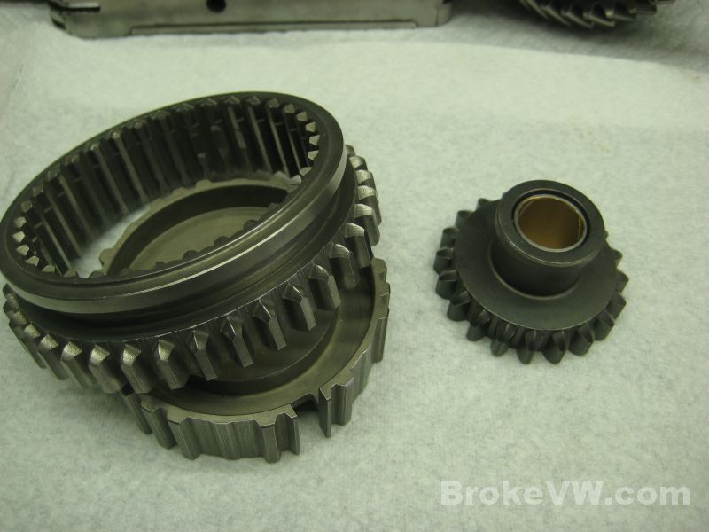
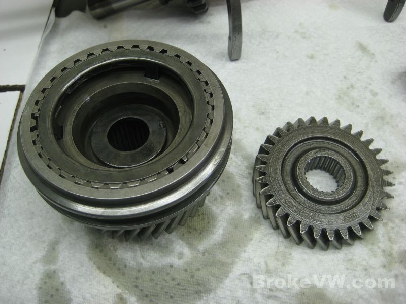
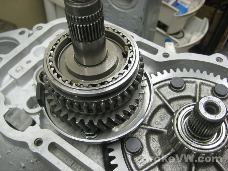
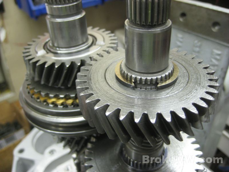
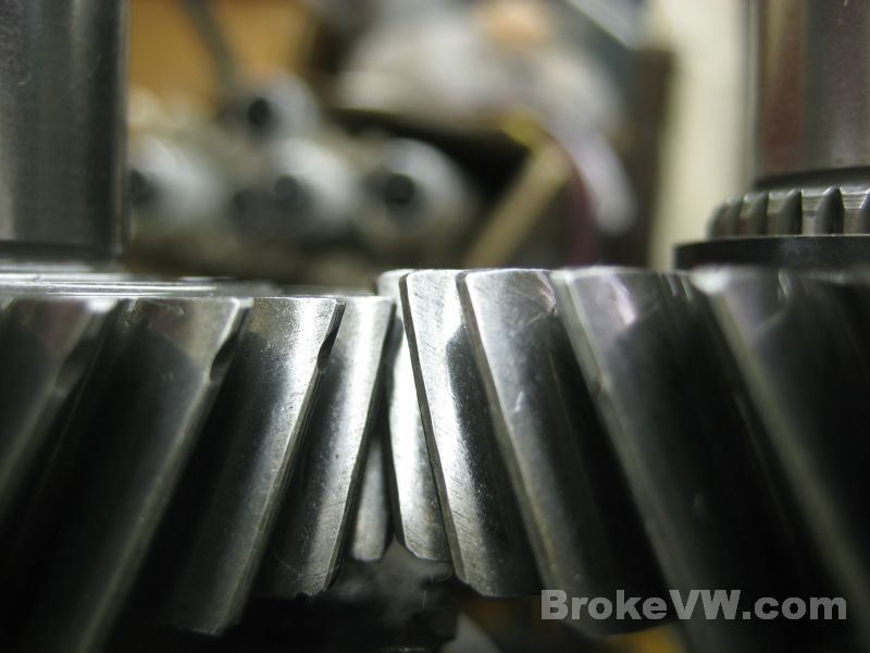
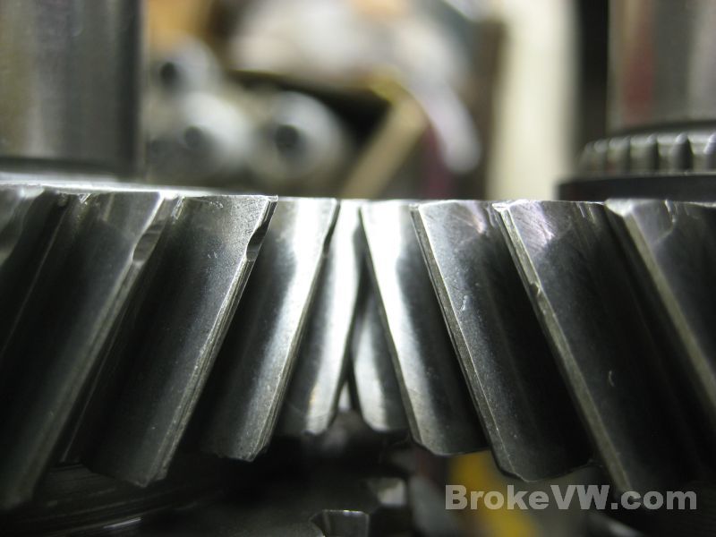
The mating gear to the reverse idler shows there has been some reverse damage at some point...
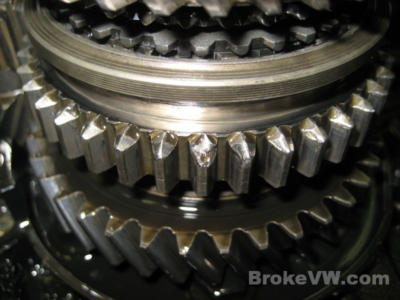
And there is is... the damage is minimal, but I would replace this reverse idler gear. The gear in the pic above... it has the top of one tooth knocked away, but the rest of the gear looks OK. I will need to inspect the small sync teeth on the assembly later once the parts are cleaned...
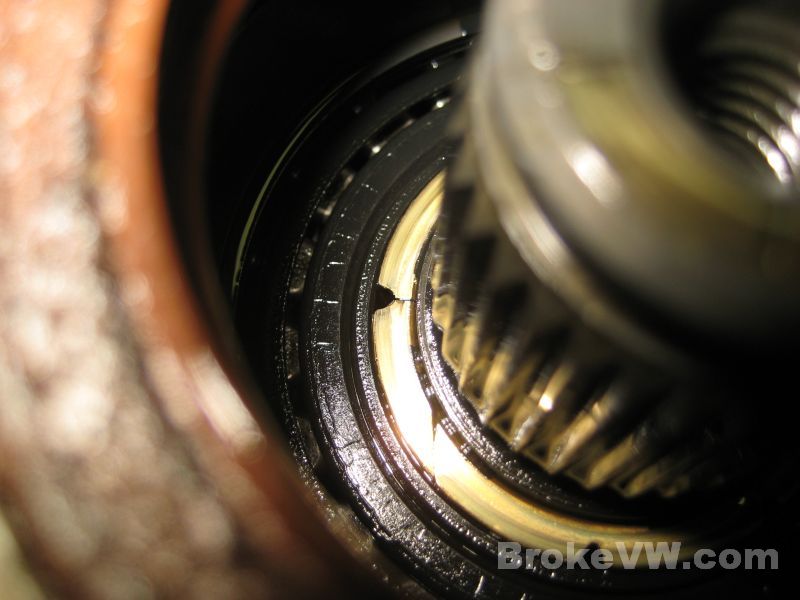
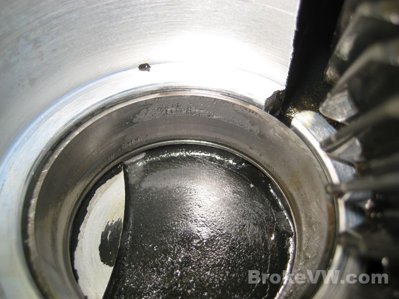
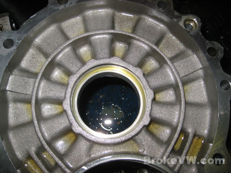
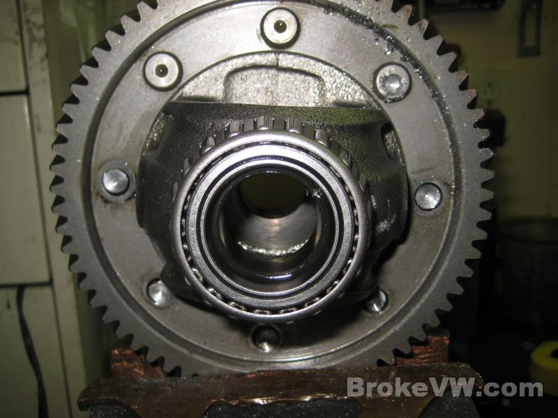
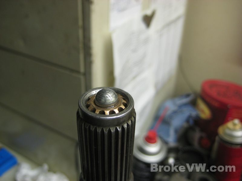
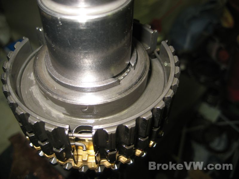
The bearing race to the small output shaft taper bearing.
This bearing is alwasy the one to show the most wear in the trans I open, it
is also the reason I started cryo treating all of the bearings I keep in
stock. It was an attempt to squeeze as much life out of these smaller
bearings as I possibly could. Your bearing was pretty bad off.
The output shaft would wobble in the bearings before I had it removed, so
this bearing wasn't far from letting go completely, and when they do the
rollers try to get out and kill the gears in the trans, so it is good this
one was pulled apart when it was...
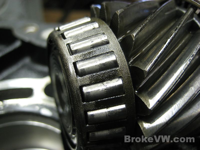
You can see the matching damage to the rollers of the bearing itself...
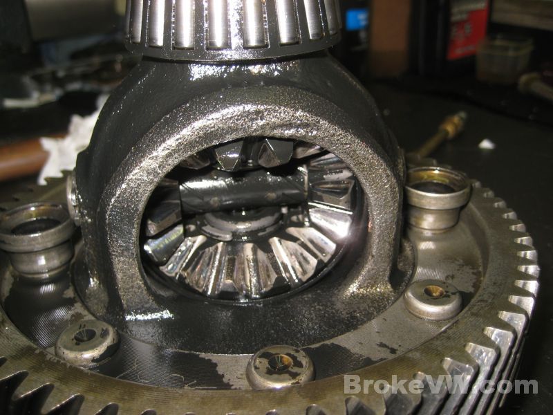
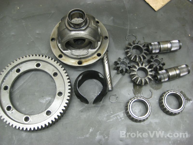
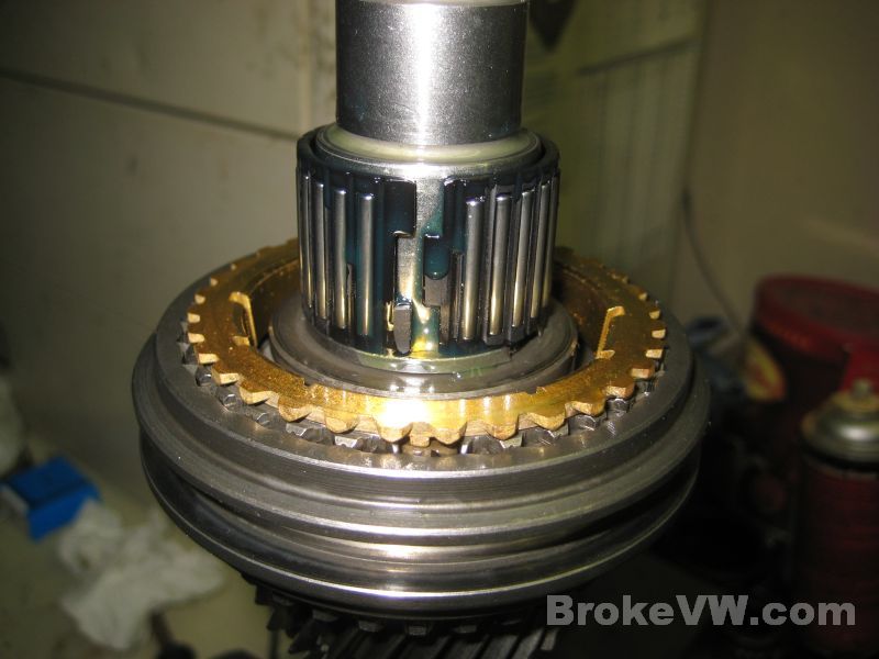
This is one of your conical thrust rings. When they are in big pieces like this and all accounted for, you can actually use them again. They can't go anywhere once everything is assembled and they'll still do their job by providing some resistance to the output stub axles to limit slop and noise....
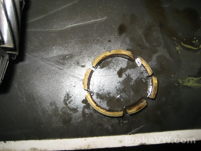
Here is the other conical ring, and it is in too many pieces to try to use again. If it is in more than 3 pieces, it should be replaced...
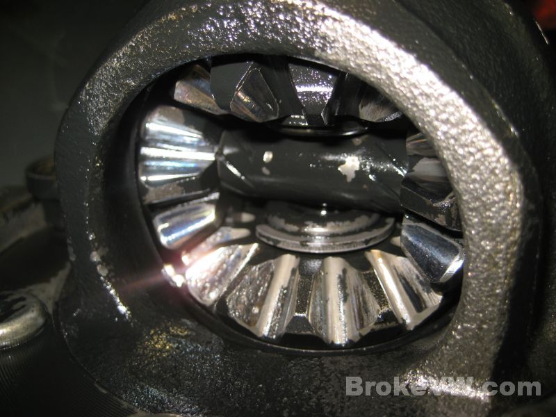
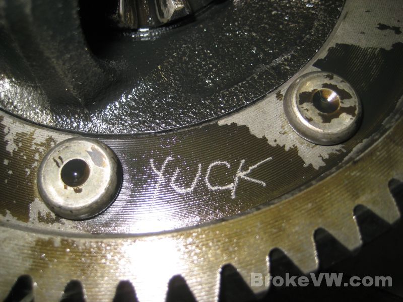
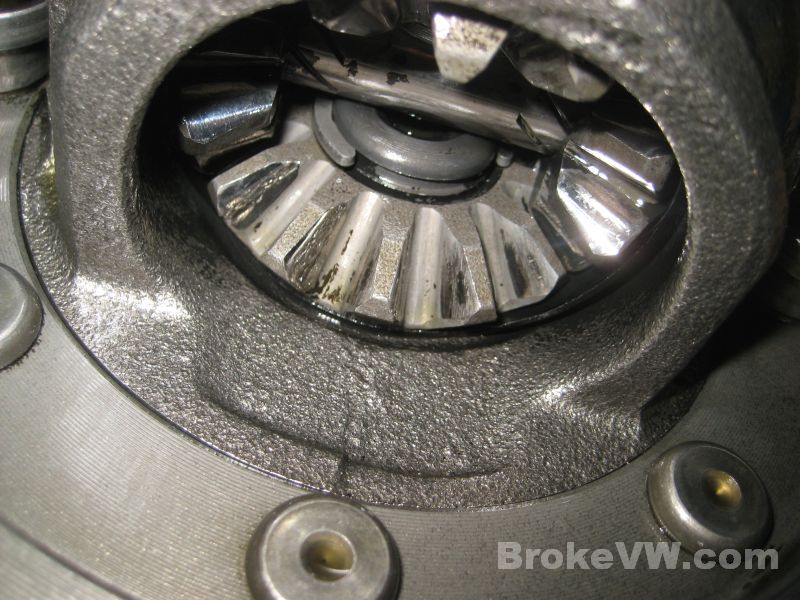
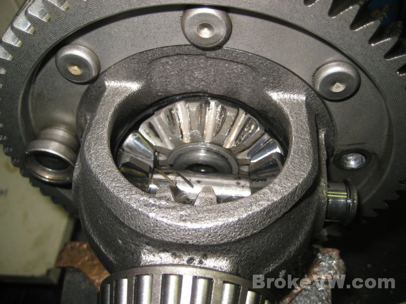
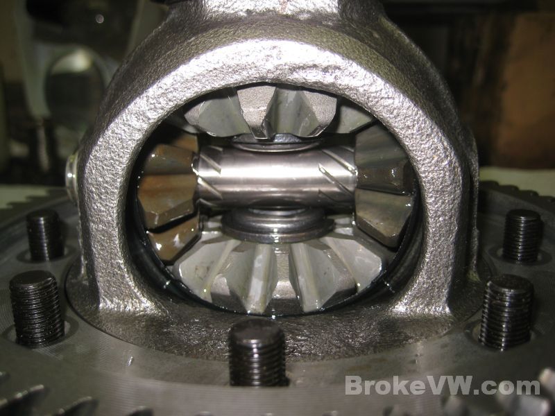
The spider gears in the diff are pretty badly pitted on the faces, they'll need replaced. The steel on the magnet was a combination of the steel from the small bearing and these spider gears, with a little from the reverse gear added. There was also a chunk of the reverse gear tooth on the magnet.
Next will be to get everything cleaned up and inspected and then start the build.
02/17/13
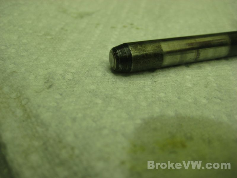
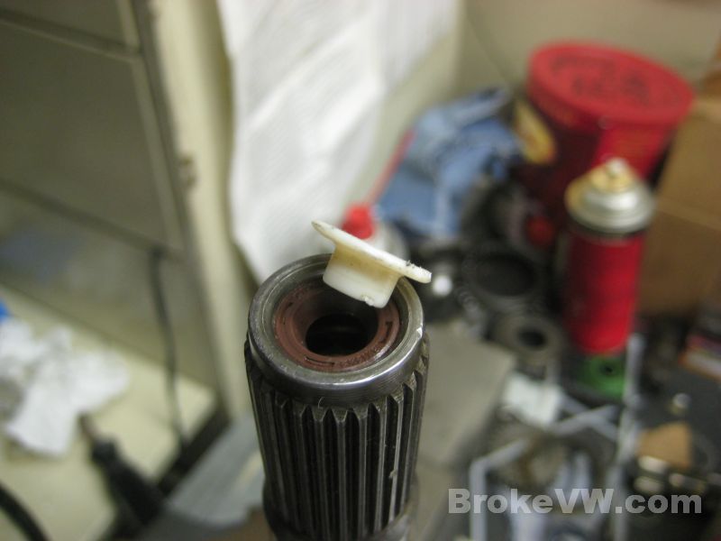
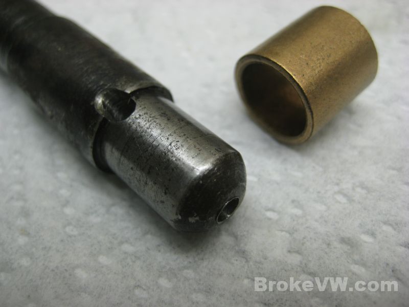
Just a couple pics of the pushrod you asked about. There is some marring in the center...
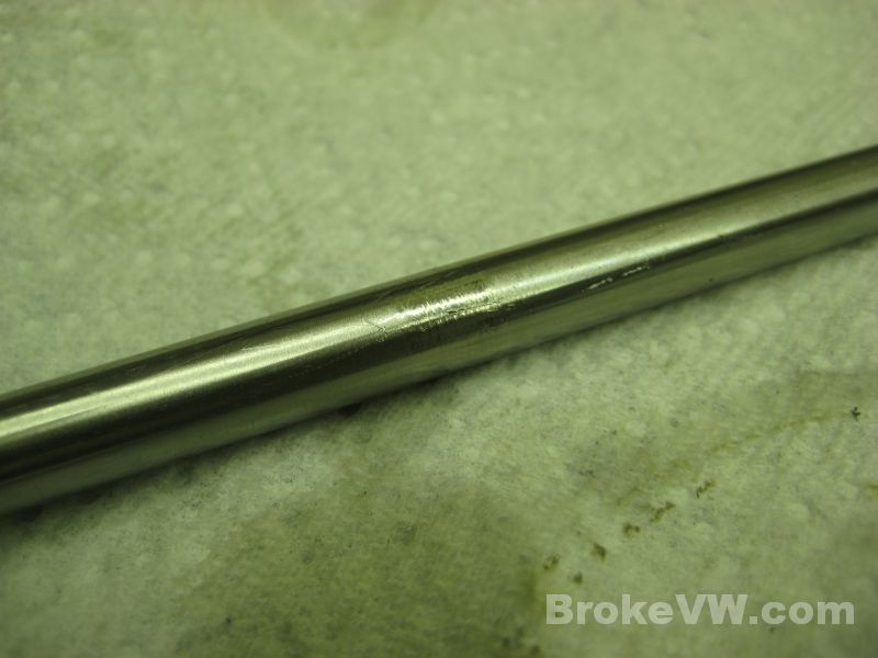
The end looks like it has some wear, it would be a good idea to order a new one with the clutch parts...
Update 03/29/13
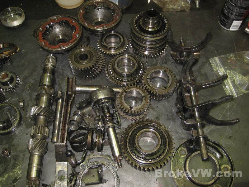
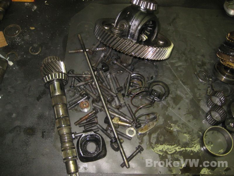
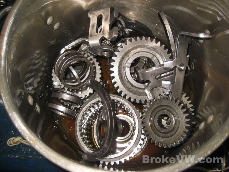
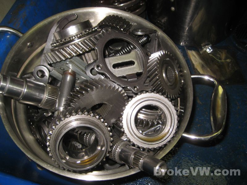
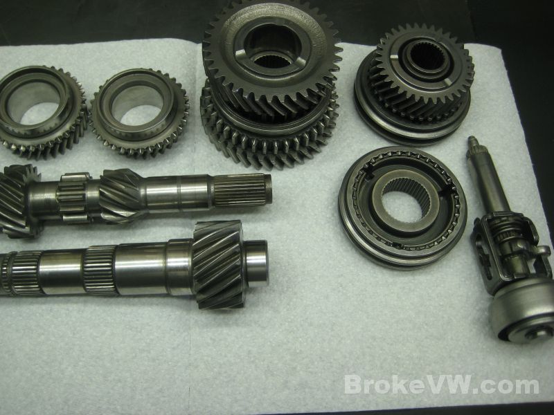
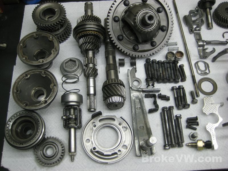
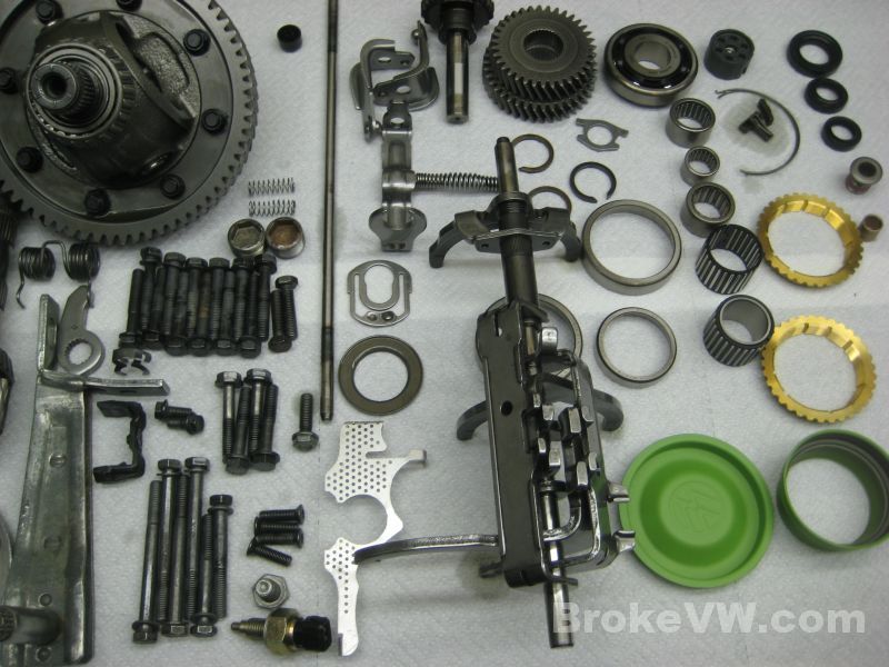
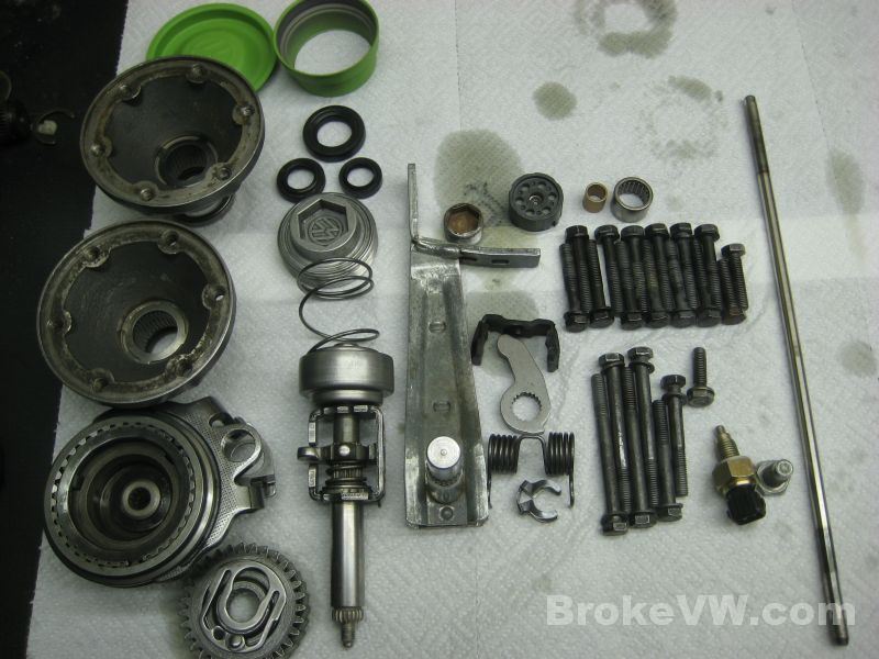
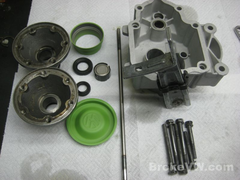
I've got your trans on the bench and have started tearing the parts down. This pic is of the parts that will be used in the rebuild that need cleaned...
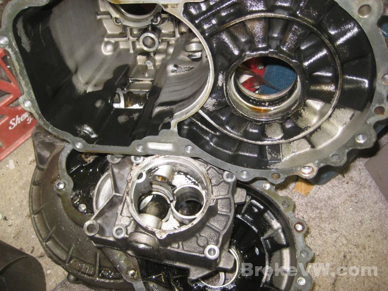
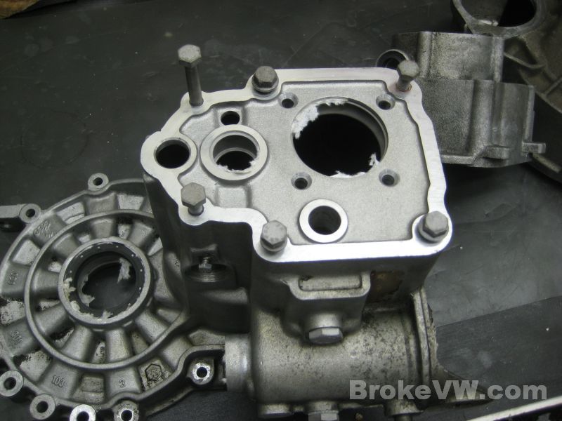
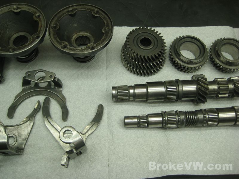
Stripping the case pieces down so they can be cleaned...
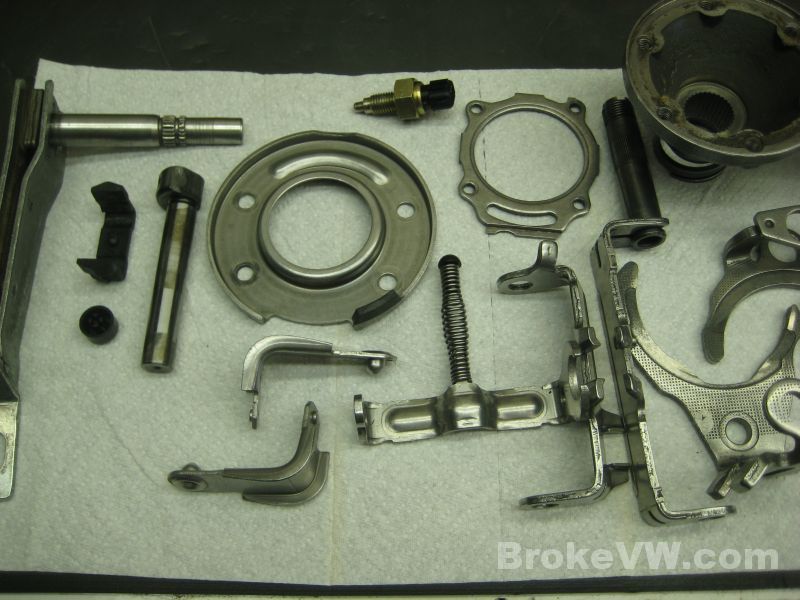
This pile of parts will be replaced in the rebuild... mostly bearings and sync rings, and a few one time use parts along with a chipped reverse idler gear...
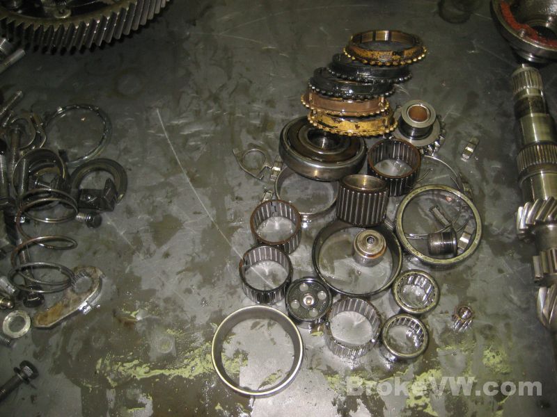
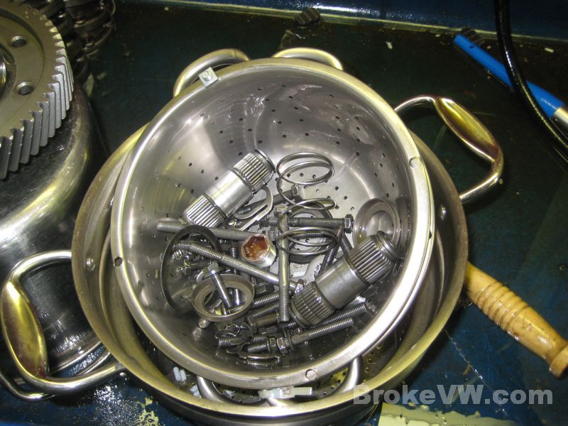
These small parts will be cleaned seperately from the larger parts because they'll get lost in the vibratory cleaner...
The casing is stripped and currently soaking in the parts washer to help loosen that black film...
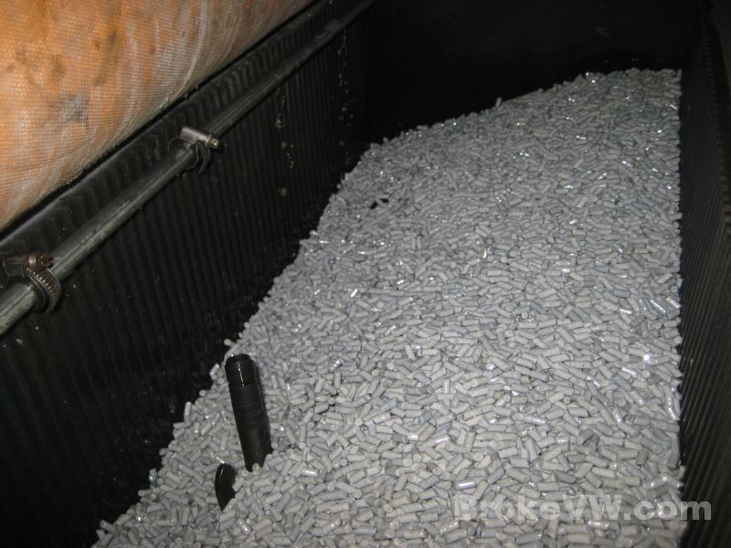
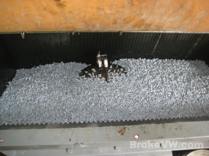
The internal parts are loaded into the vibratory cleaner...
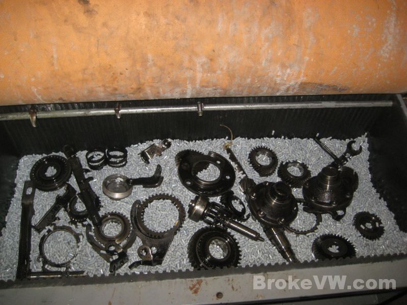
They'll be left to tumble around and get cleaned up as I work on the casing...
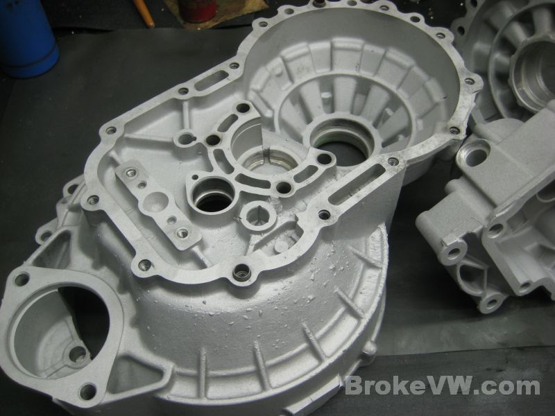
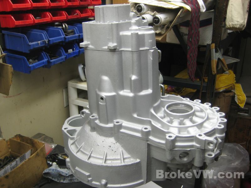
A befor and after comparison of the bellhousing. It's clean enough at this point to prep it for media blasting. Next will be working on the gearbox half of the casing...
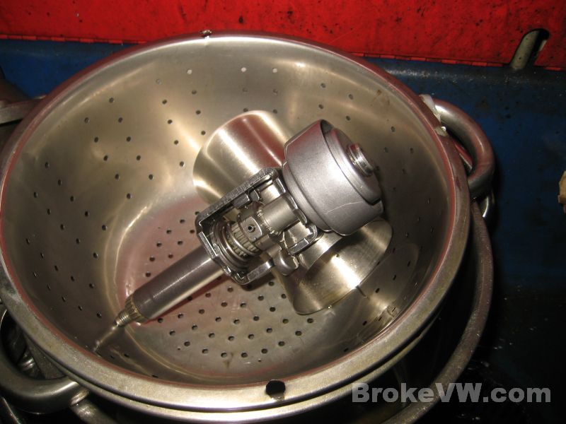
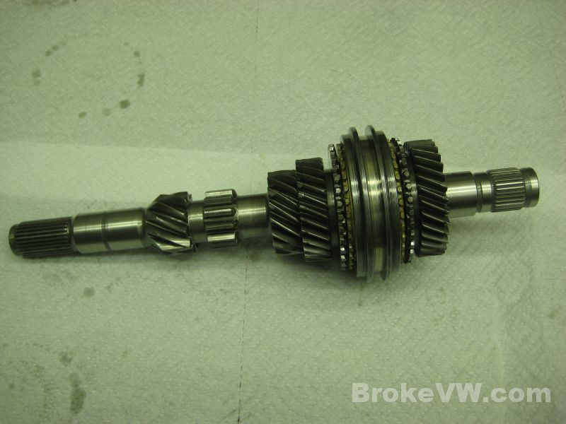
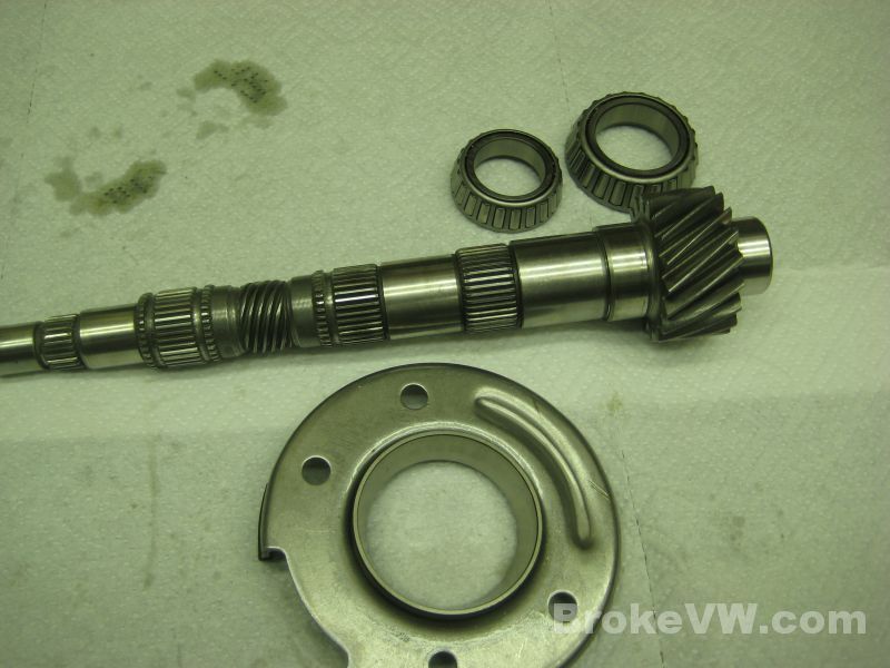
Stripping the output shaft to get it into the cleaner...
The internal parts out of the vibratory cleaner and being rinsed in the parts washer...
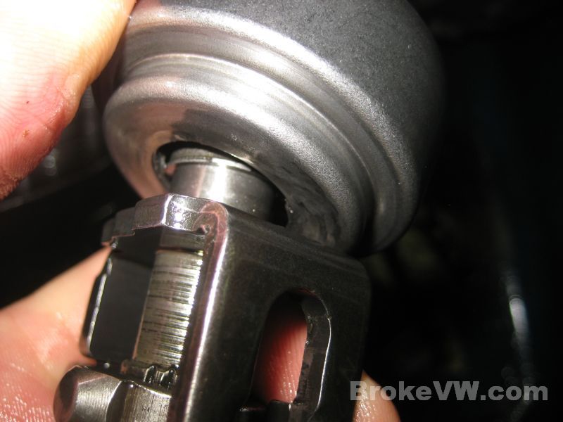
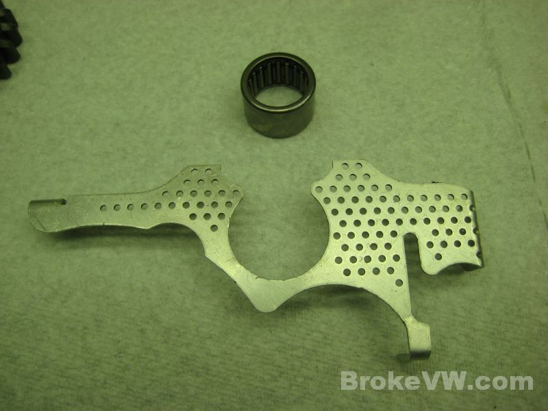
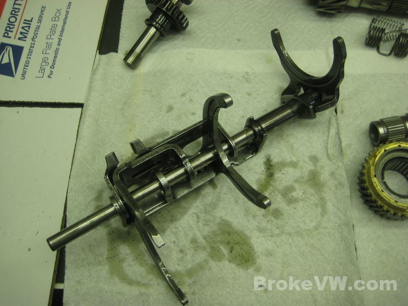
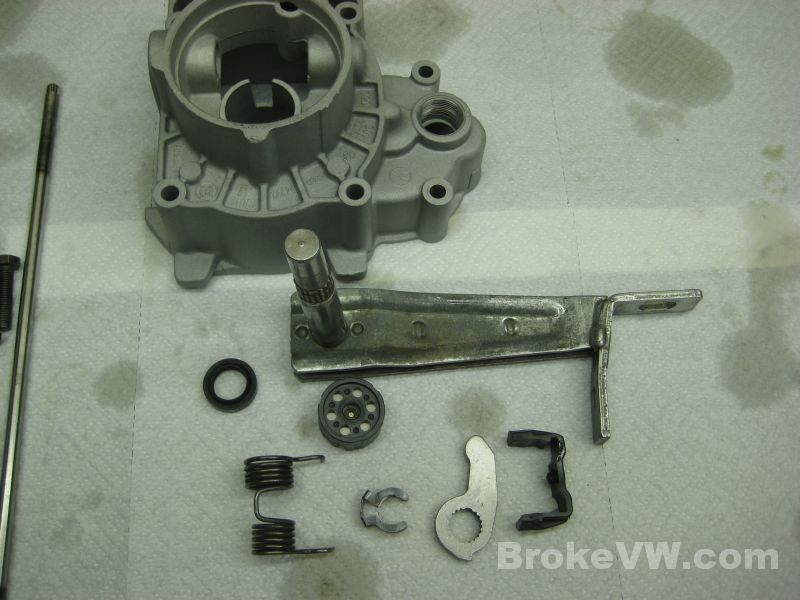
The selector assembly has a broken guide tube. It isn't common, but not the first time I have seen this happen.
Update 04/01/13
I've picked out a replacement selector for the rebuild to replace the broken one above, if you have a spare selector kicking around you want to send it will save a little money over replacing your broken part with one from my stock...
A couple pics of the nasty film that develops on all the internal trans parts on those trans that don't get regular fluid changes (which is most of them).
The inside of the gearbox is soaking to loosen the film up so I can remove it. I use a nylon brush to get the bulk out, then for the corners and tight spots I use q-tips to scrub the film away....
Once cleaned with the q-tips, they look nicer...
The internal parts draining, I'll next rinse the kersosene away, dry them fully, then immediately oil them. They'll go into bags to be protected from dust and contamination, already oiled and ready for assembly later...
Everything as it sits now in he parts washer, I still have work to do on the gearbox casing with q-tips, then on the bellhousing, and the diff needs cleaned and then the rivets drilled and the diff stripped down. Once the diff is stripped and cleaned the internal parts will be close to complete and ready, leaving only the casing to prep for media blasting...
Update 04/06/13
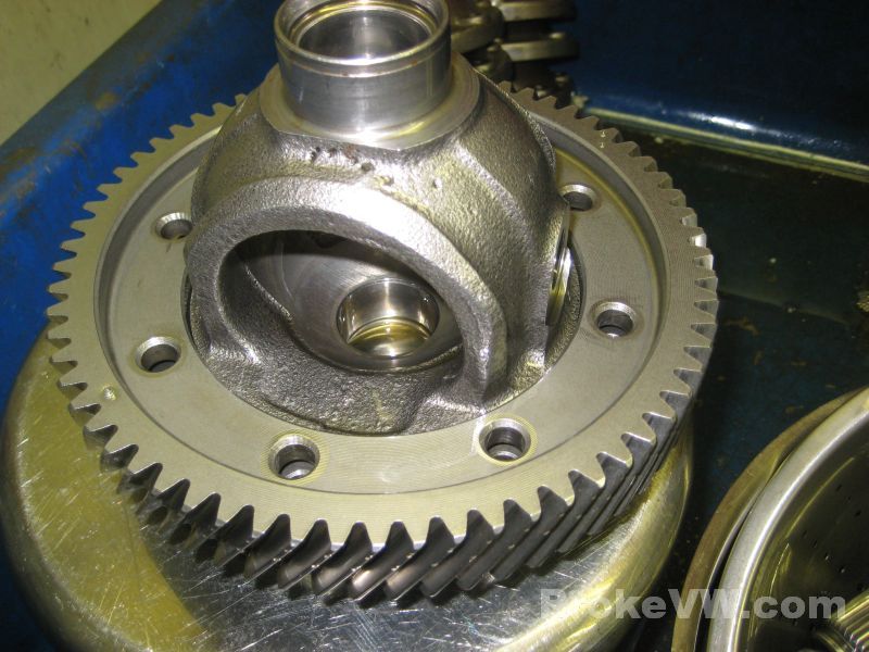
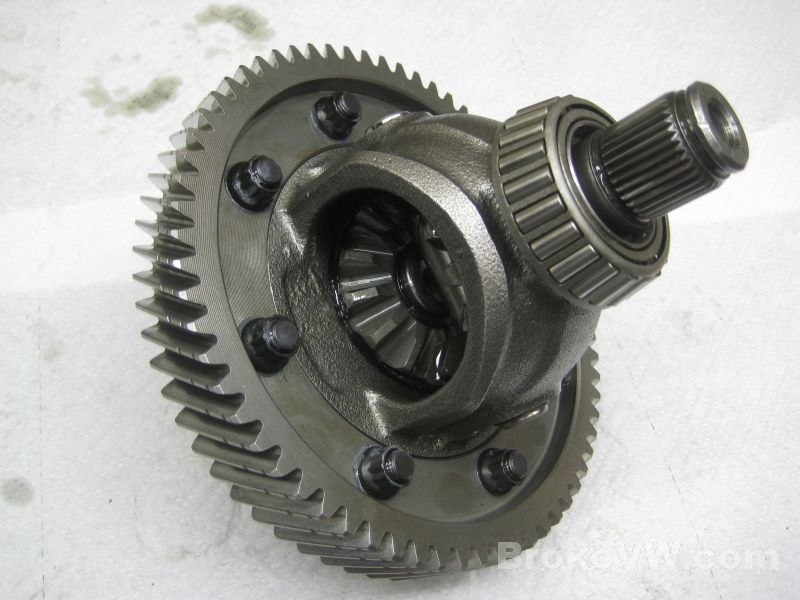
I have the diff out of the cleaner and it is rinsed off, next will be pulling the bearings, drilling the rivets, removing the spider gears, and finally removing the ring gear so everything can be cleaned again once exposed...
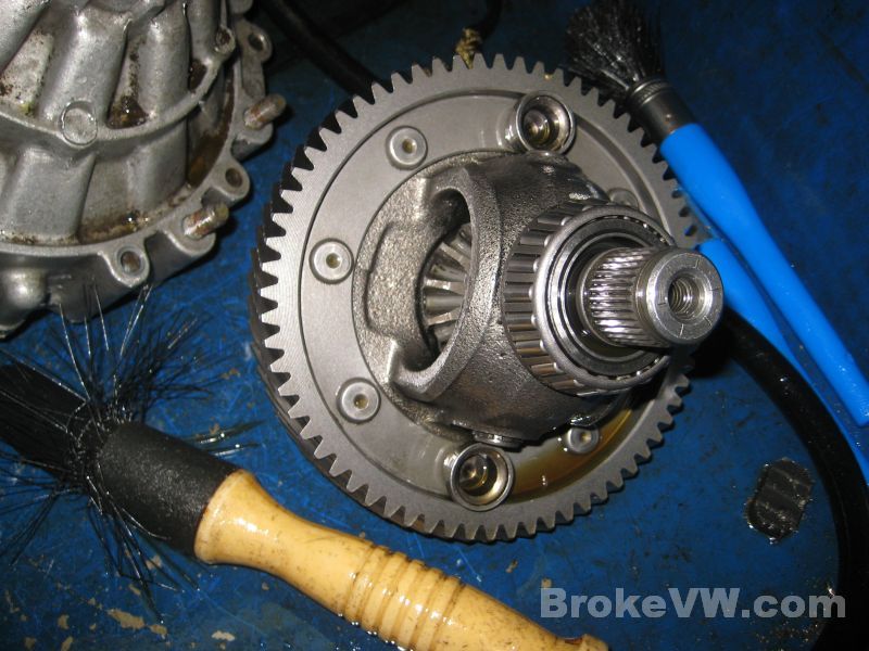
Your diff spider gears are pretty chewed up, I will replace them when I rebuild it...
Update 04/10/13
The case is prepped for media blasting by plugging all of the threaded bolt holes and the bearing and seal bores with old bolt, seals, and bearing shells. The plugs I use are ground down so they are no longer a press tight fit... to keep them in place I put a piece of paper towel between the bearing and the bore to take up some slop and get the bearing to fit in snugly. They tap out easily and the towel is discarded....
With one of the large head rivets removed, the spider gears and cross shaft can be removed from the diff...
Drilling out the rest of the rivets to finish stripping the diff...
With the rivets drilled the studs are punched out in the press and the ring gear pressed from the carrier. The carrier and ring will go into the parts cleaner and the casing will be media blasted the next chance I get to do it...
Update 04/15/13
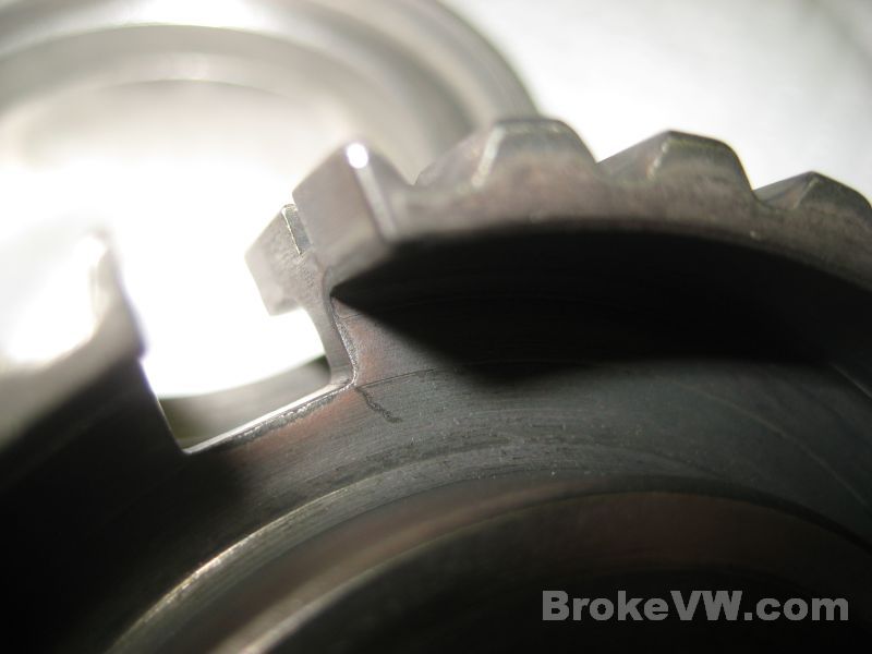
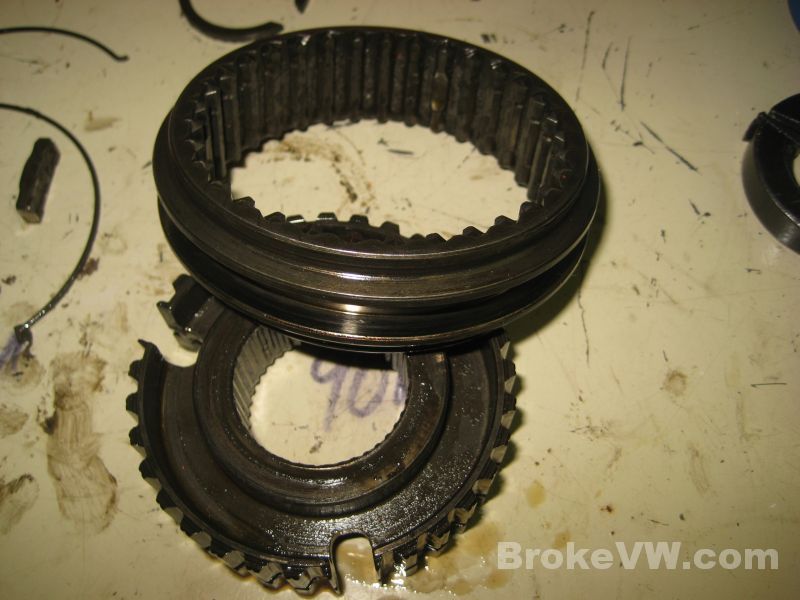
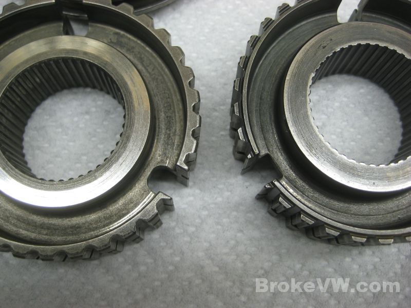
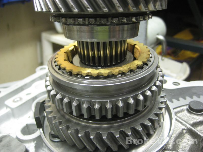
With the parts fully cleaned they can be inspected for things like cracked sync hubs, which you have. The 3rd/4th sync hub is bad for cracking at the corners of the key slots. VW addressed this problem later with updated sync hubs with rounded slots for the keys, to reduce the stress points in the corners. I'll replace this hub assembly...
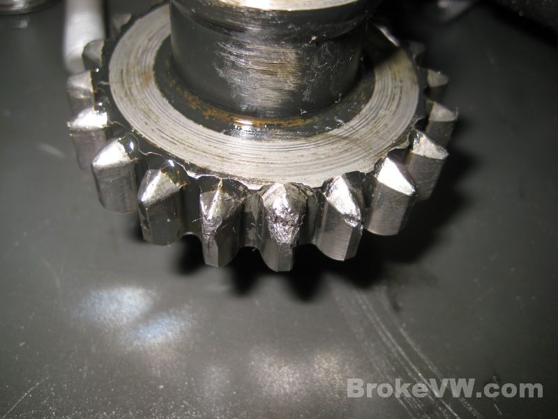
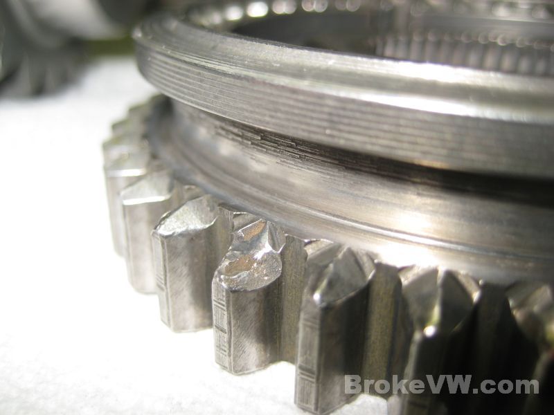
This is the damage I found on the 1st/2nd sync hub assembly which is the mating gear to the reverse idler gear, which has matching tooth damage....
Here are the internal parts cleaned and dried, ready to be oiled and assembled. I have tried a new method of preparation with your parts... I take them from the kerosene parts washer into a laquer thinner bath, then rinse them with more thinner and air line them dry. It seems to work well enough and saves me a little time...
The smaller internal parts as well as the case bolts and other small pieces are put into a cleaning ball I made from 2 strainers bolted together and filled with the cermaic tumbling media...
The small parts cleaned up being rinsed in the kerosene parts washer, next to be taken to the thinner bath and then they will be ready for the rebuild...
The diff carrier and ring gear cleaned and rinsed, ready to be rinsed again in thinner like the small parts above...
I will be media blasting the casing soon, this is something that I have to take to another location to do because I don't have the compressor to run a blaster here. I have a couple places I can drag everything to (I bring my own blaster, media, parts, hood, breather, etc. with me) but the next step in your rebuild is to partially assemble the small parts, get everything oiled and bagged up and put away, then focus on the casing.
Update 04/17/13
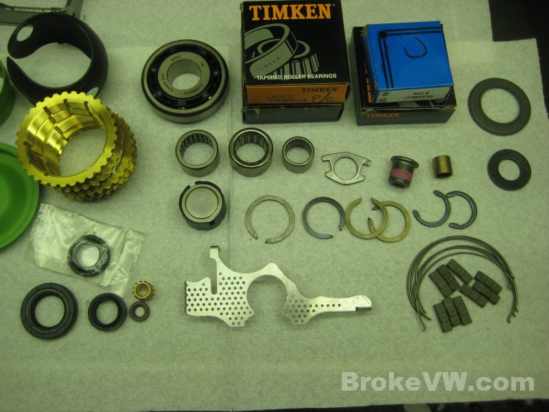
Here are the new parts that will be used in your trans...
The new reverse gear set...
This bearing is the NLA bearing in the 5th housing, but I was able to source open ended bearings from the same mfg. in Germany (INA/FAG) and have them cryo treated, your trans will get a new bearing in the 5th housing. Also shown is one of the strainers VW puts into the newer 020 trans, I will be installing one into your trans when it is built...
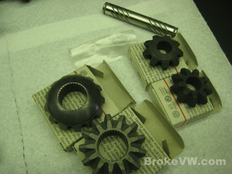
The new OE VW spider gear set...
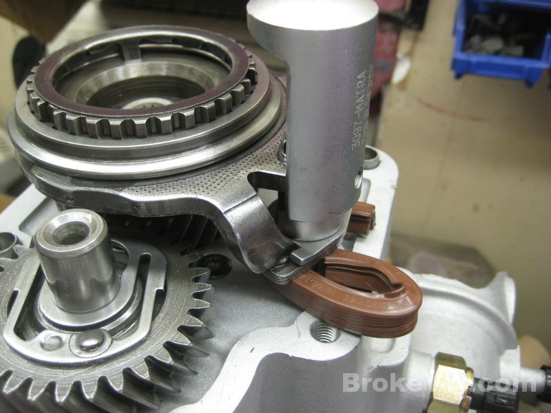
This is your actuation finger, they are known to crack when they fail. I don't see any signs of cracking with this one, and the wear isn't much at all on the end that contcats the TO bearing. I can replace it now with a new VW part or leave it... I would probably leave it if it were my trans. If it fails later (they all do eventually) you'd need a new green end cap and finger to sort it out and they are $50 new so I would suggest keeping it...
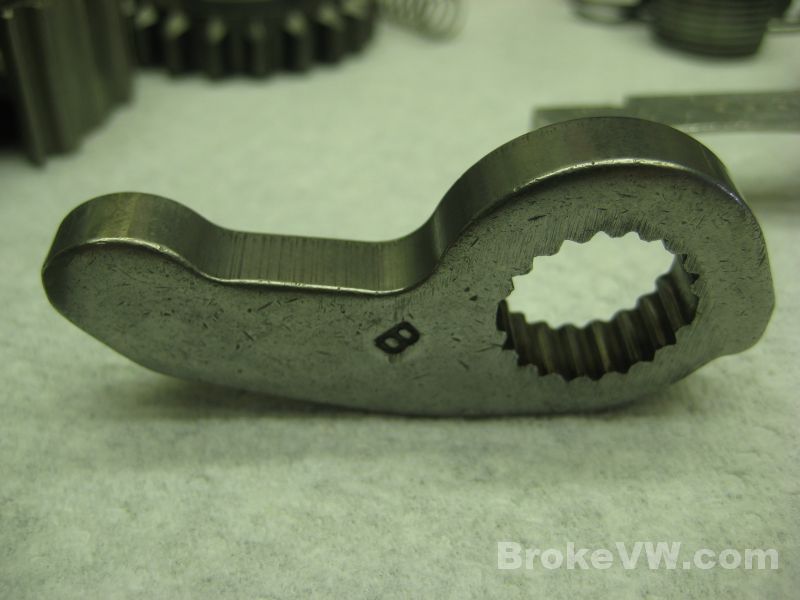
The very minimal wear on the tip of the finger...
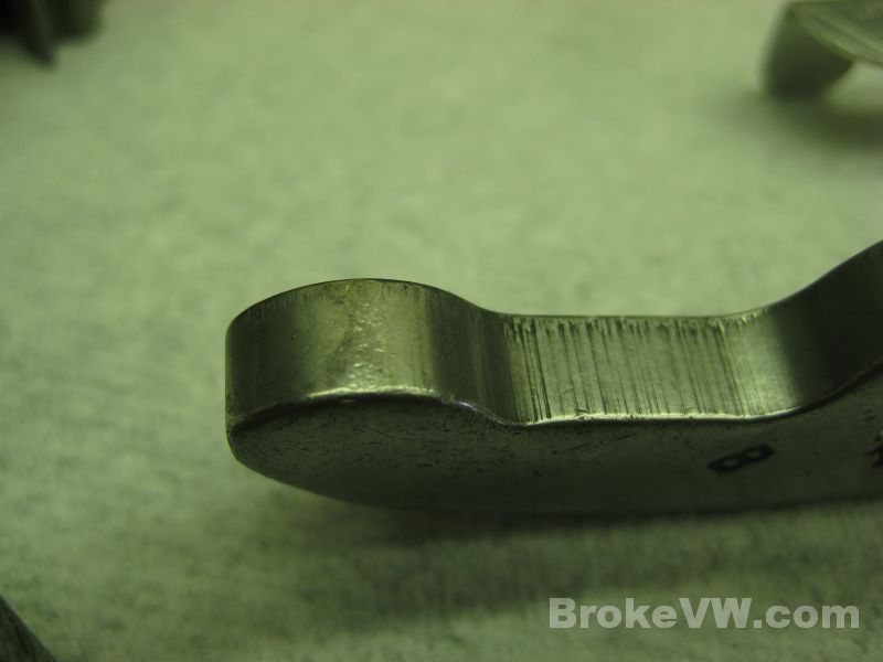
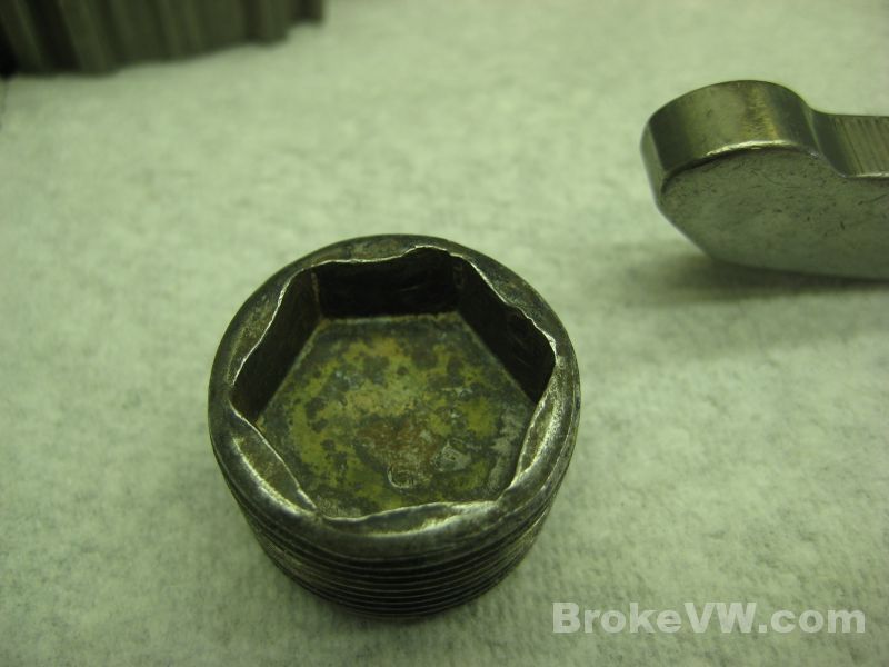
This is the drain plug in your trans, and I think I would replace it... the corners are starting to round out and if it gets tight on you after time it might round out when trying to remove it. I have new OE VW drain plugs if you'd like one, they are the 020 Syncro plugs which are exactly like the usual 020 plugs but these have a magnet in the end and are fitted to the angle drive units on the AWD cars that use the 020 Syncro trans....
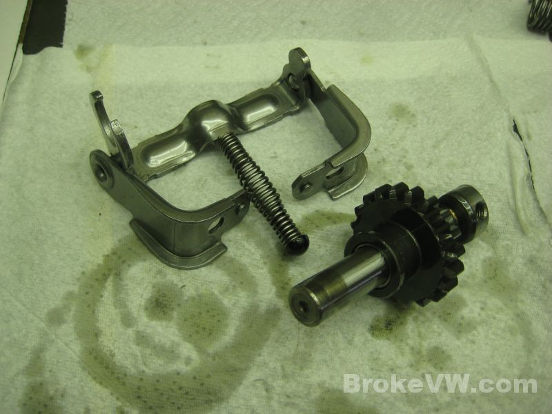
Your 5th assembly is built and complete with new springs, keys, sync ring, bearing, and 5th washer...
Same with the shift forks and the reverse gear and reverse relay lever assemblies, they are assembled, oiled, and ready for the rebuild process...
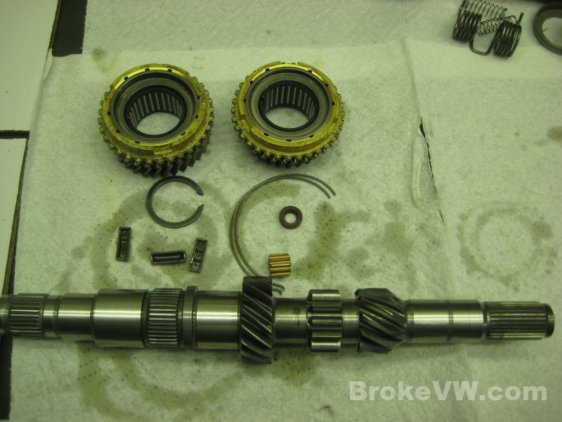
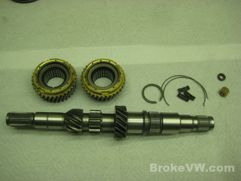
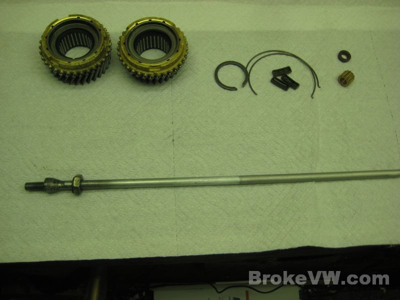
The new parts to be used to build the input shaft are the pushrod seal and bushing, 3rd and 4th needle bearings, 2 sync rings, the springs and keys, and an input shaft circlip. The only thing missing is a 3rd/4th sync hub...
Here is the 3rd/4th sync hub... it's from a March 1997 DFQ MK3 trans, it is the newer updated style of hub that uses the rounded cuts for the sync keys, which prevents the hairline cracks that your old hub had. The hub and sleeve are in the parts washer now being cleaned...
When the parts aren't being worked on they stay covered to prevent any dust from settling on them....
The assembled parts are oiled and bagged up and put away until they are needed for the rebuild...
I'm currently trying to dodge thunderstorms to get your casing blasted and am building the sub-assemblies of the trans while I wait to blast.
Update 04/19/13
I was able to get your trans blasted this evening, I just got it finished before running out of daylight...
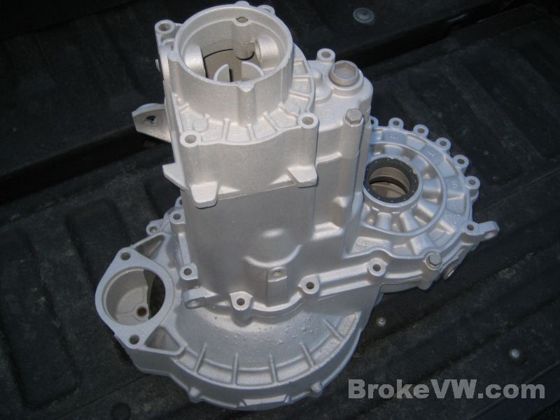
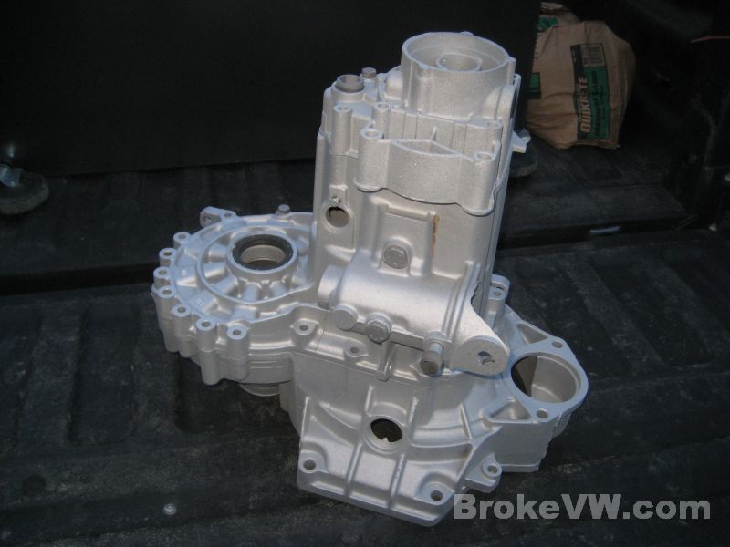
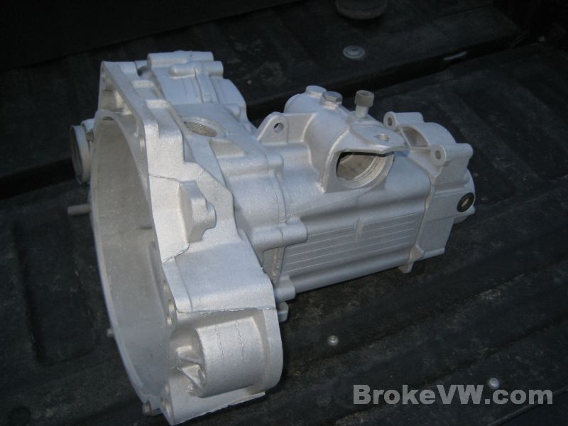
I have to rinse it all off fully and remove the dummy seals and bearings and rinse it again, then it should be ready to go onto the rotisserie to start assembly.
04/22/13
Here is the replacement 3rd/4th sync hub that your trans will get, on the left. It has rounded slots for the keys that reduce the stress points in the corners of the old slot design on the right...
Back to assembling the input shaft...
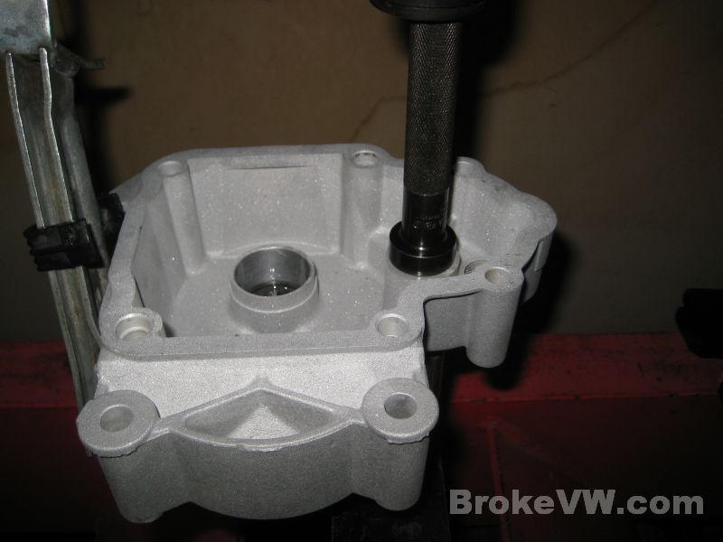
This is a tool I made for entending the reach of the dial indicator but it works quite well for installing the pushrod bushings nice and straight without distorting them...
The shaft is held in the vise and the pushrod inserted through it until I can hammer the bushing in flush. The pushrod staying inside ensures the ID of the bushing doesn't distort during the install process, which can sometimes happen when you hammer them in without supporting the inside of them...
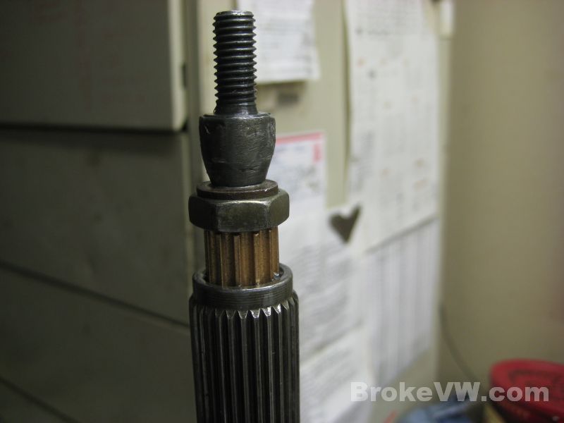
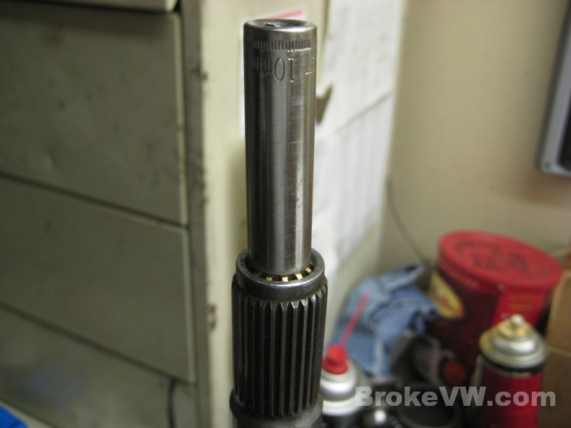
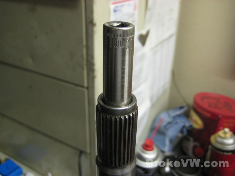
Once the bushing is flush the pushrod tool is removed and inserted in from behind to continue to support the ID of the bushing, then a deep 10mm socket is used to drive the bushing the rest of the way in while the pushrod and shaft remain stationary...
The pushrod tool is supported from below by resting on the vice jaw...
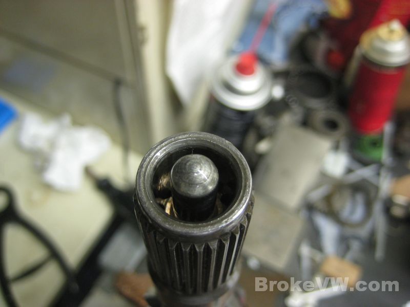
The pushrod seal is installed with a small plug insert which is actually the installation tool. It is popped into the center of the seal and the top of the plug is 0.8mm to 1.3mm thick or so. The seal and plug is driven into the end of the input shaft flush, then you pop the plug out and the seal is left the proper depth which is.... 0.8-1.3mm below flush :)
The 3rd gear bearing and gear and sync ring are installed...
The replacement hub is heated to 210F and pressed on with a new sync spring...
The top sync spring is added and the circlip is installed to secure the hub...
The 4th bearing and sync ring are installed, leaving only 4th gear to slide on to complete the input shaft for the rebuid...
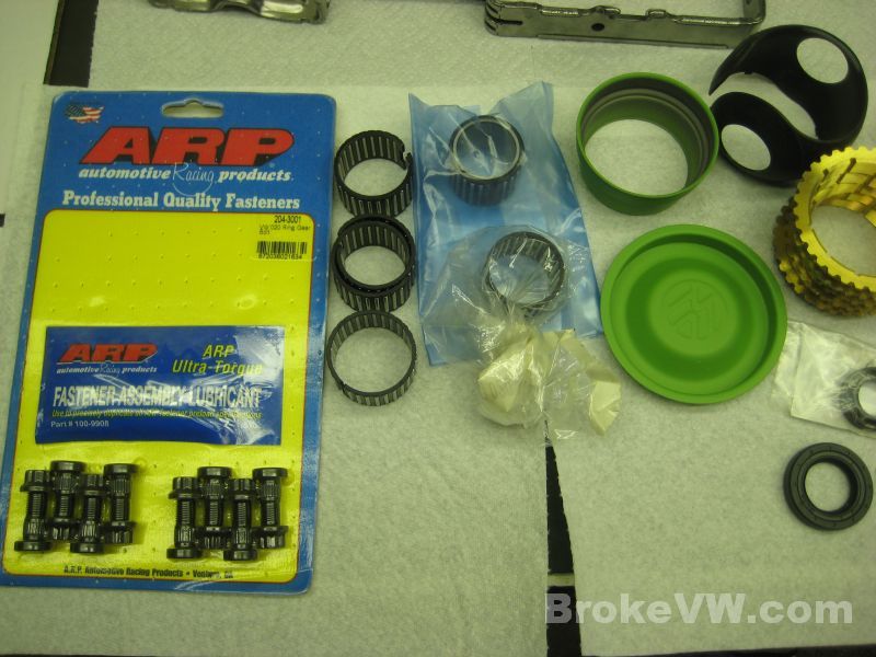
Next the diff needed built, everything is shown here except for the new bearings. New ARP bolt, plastic diff thrust piece, new spider gears and cross shaft, and new 2.3mm snap rings for the output stubs which are 0.3mm thicker to take up slop in older parts (which is basically the carrier and stub axles at this point)...
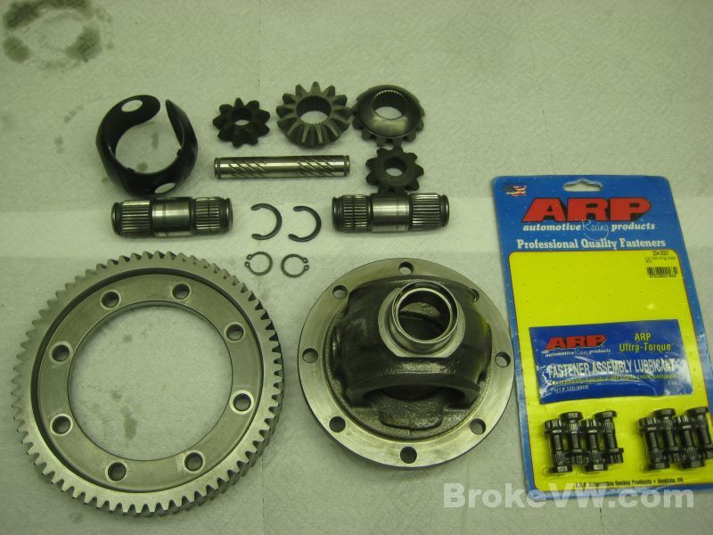
The ARP studs are pressed into the carrier...
The ring gear is heated to 210F and pressed onto the diff carrier...
The bearings are also heated to 210F and pressed onto the carrier...
The new plastic thrust piece and spider gears are installed, and the thicker 2.3mm snap rings are fit to the stub axles.
ARP assembly lube is used on the studs before installing the
nuts. I like to run a small bead up the side of the threads and over the top, to
ensure there is grease pulled into all the threads as well as under the head.
The friction between the head and ring gear and the threads themselves take up a
considerable amount of the install torque.
When you tighten the nuts to 52 ft-lbs, a certain percentage of that is used to
overcome friciton, and is not put into clamping the parts. When the threads and
underside of the nut are properly lubricated you can lower the install torque
and still get the same clamping force since less of the torque will be used
through friction...
The diff is assembled and it is nice and tight, and will be tighter with the addition of the 80% kit during the rebuild...
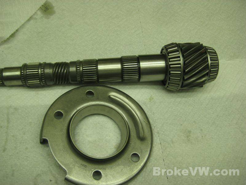
Lastly I pressed the bearings onto the output shaft and into the bearing retaining plate...
With the internals done, I moved onto stripping the case the rest of the way. The starter bushing is pulled, along with the rest of the dummy seals and bearings and bolts...
The case will now get rinsed out a few times then it'll be time to start pressing races into the case to begin the preload procedure and the actual rebuild...
Update 04/23/13
I've rinsed the casing out and it is ready so the parts are all laid out to begin assembly...
The casing is sprayed with WD40 to keep the surface wet so any dirty fingerprints that get on it during the build process will wipe off easily. The WD40 will evaporate away fairly quickly but the dark or wet spots you see on the casing in the following pics is from the WD40....
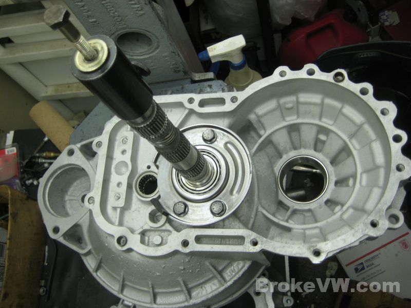
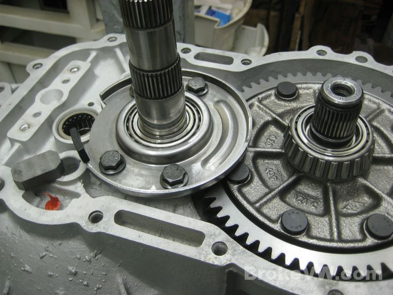
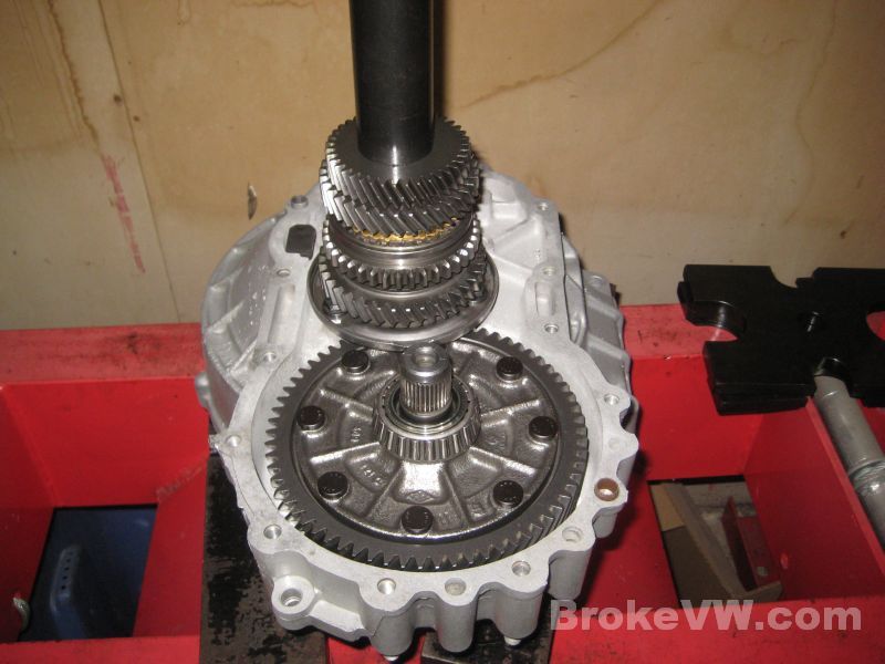
The bearings and races are pressed into the bellhousing, the output shaft got the shim that I removed from the trans put back in place and the diff race got the standard 1.0mm shim behind it...
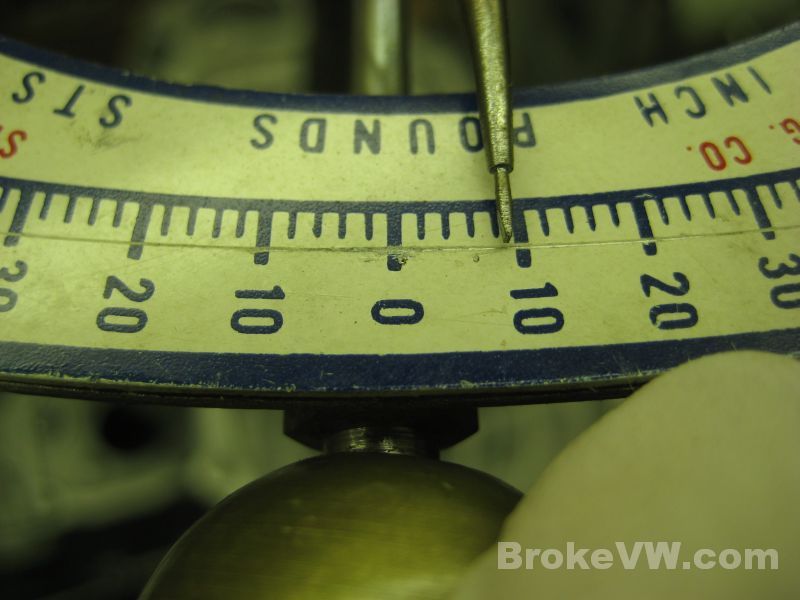
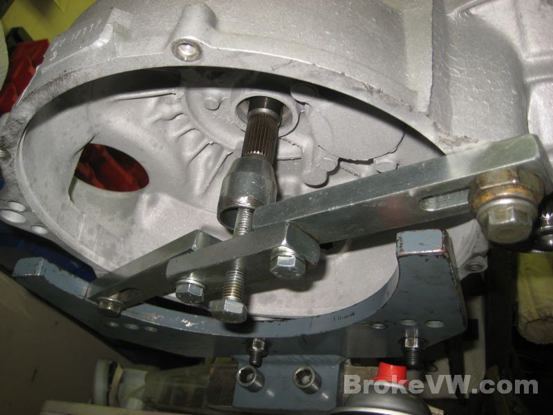
The output shaft is mounted up and the turning torque checked to see if the preload is in spec...
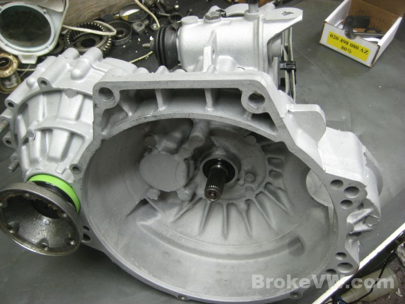
VW spec is 4.4 to 13.3 in-lbs and I like to try to get in the middle of the VW range which would be 8.85 inch-pounds.... your output preload is about as close to perfect as I could hope for so it is done...
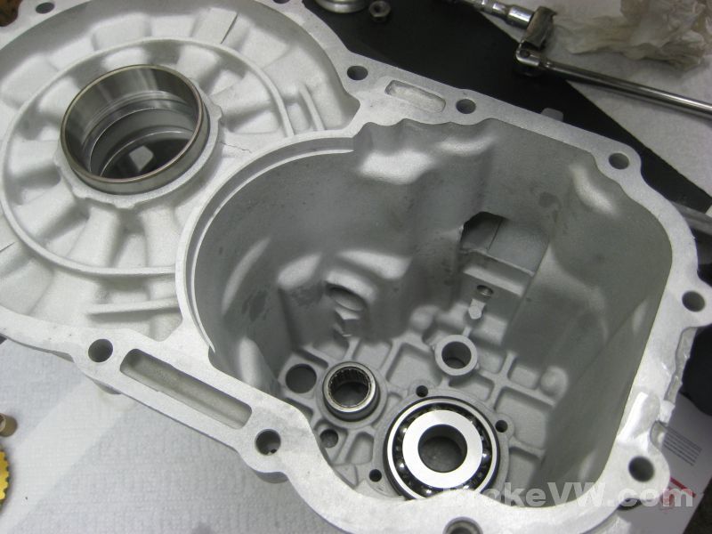
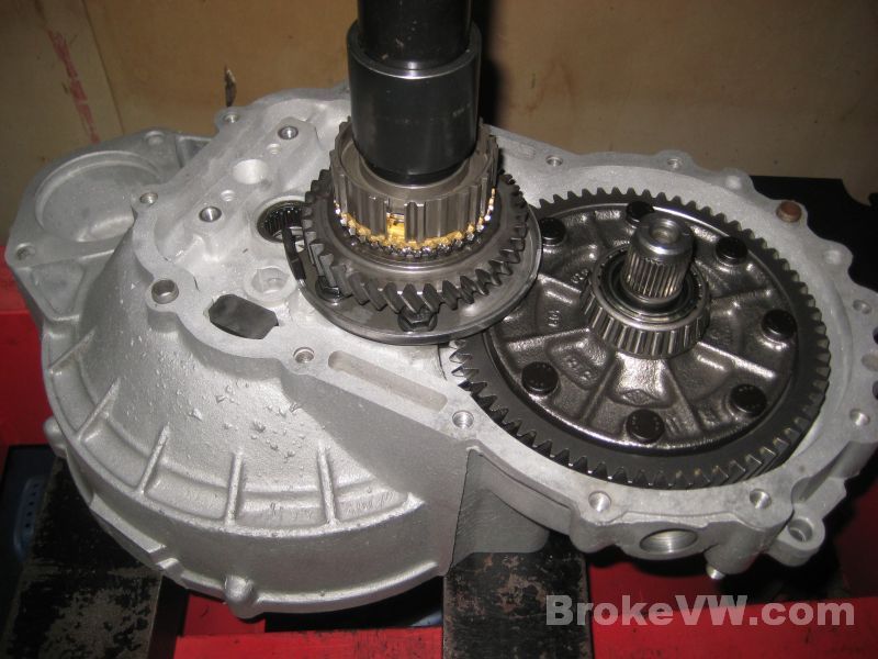
With the output shaft preload complete, it is time to move onto the diff preload so the bearings and races are pressed into the gearbox half of the casing, and I started with a 1.0mm shim under this diff race...
With the diff installed and 5 case bolts tightened down the diff turning torque is checked...
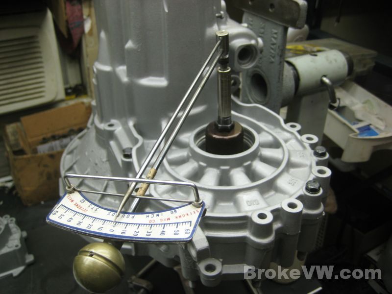
VW spec is 11-31 in-lbs. so the middle of the range would be 21 in-lbs, your preload came out absolutely perfect... if it was the output shaft... but it isn't so it is too low...
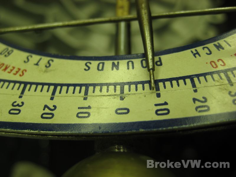
I removed the race and added 0.15mm of shim and checked again and while this brought it into VW spec, it was just tight enough to pass and I like to get it a little closer to the middle if I can, so I pulled the race again and removed the 0.15mm shim and added a 0.30mm shim...
With the 0.30mm shim added it felt a lot better and I am happy with the 19 in-lbs. preload the diff has so the preloads for the trans are now complete....
I'm waiting on a couple 80% kits to show up, and I still need to media blast the 27mm selector cover to your trans, but the rest of the work is just assembly at this point and it should be completed shortly.
I went ahead and stayed up a little late and got more work done since I'm not sure how much time I'll have in the next few days. I have the internals assembled and the casing is ready to go back together. The 5th housing needs built, and then the 80% kit needs to arrive and get installed, the flanges and 5th gears need to go on, then it should be done.
The input shaft is bolted in, the magnet is secured with RTV, and the shift rod spring is dropped into the blind hole. The screen I wanted to install doesn't seem to fit the older retaining plates so I wasn't able to use it...
Pressing on the new 1st/2nd sync hub assembly after installing the 1st gear and new 1st gear parts...
The completed sync hub, ready for the 2nd gear needle bearing to be installed...
With the needle bearing installed 2nd gear and a new sync ring are dropped on...
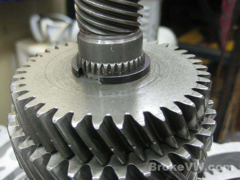
3rd gear is pressed on...
It is secured with an adjusting circlip, most trans take the largest 3.0mm, some need only a 2.9mm, but the procedure is to fit the largest possible so your trans needed one just a touch thinner than 3.0mm but it could use a bit more than 2.9mm so I thinned a 3.0mm circlip down a little at a time until it fit perfectly...
The lower 4th circlip is installed, and the input shaft dropped into place...
The 4th gear and upper circlip are installed...
With the input shaft simply resting in the trans on the roller bearing, the gear alignment is not correct and any press forces into the shaft will be transmitted into the bearing or gears...
A VW support bar is bolted across the bellhousing and supports the input shaft so all forces pass through the input and are spread across the bar and bellhousing....
It also allows for adjustment of the input shaft height so proper gear alignment can be achieved...
Reverse gear and the releay lever and uprights are installed...
The shift forks are swung into place...
This is what remains to be installed, along with the missing 80% kit...
The trans as it sits now, I'll get the gasket surface prepped and get sealant paste on it and will get the casing closed up, then I can work on finishing the rest of it and last will be to install the 80% kit and flanges....
Update 04/25/13
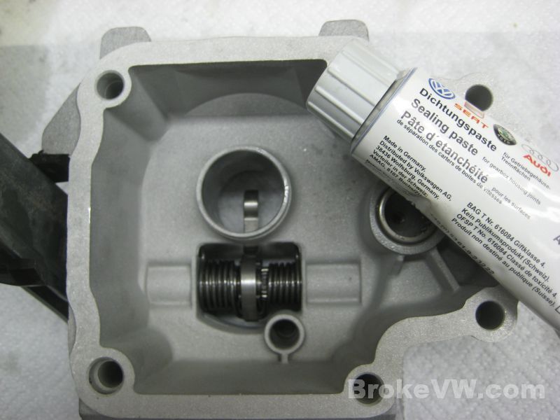
Time to assemble the 5th housing parts...
The greased release arm seal is installed...
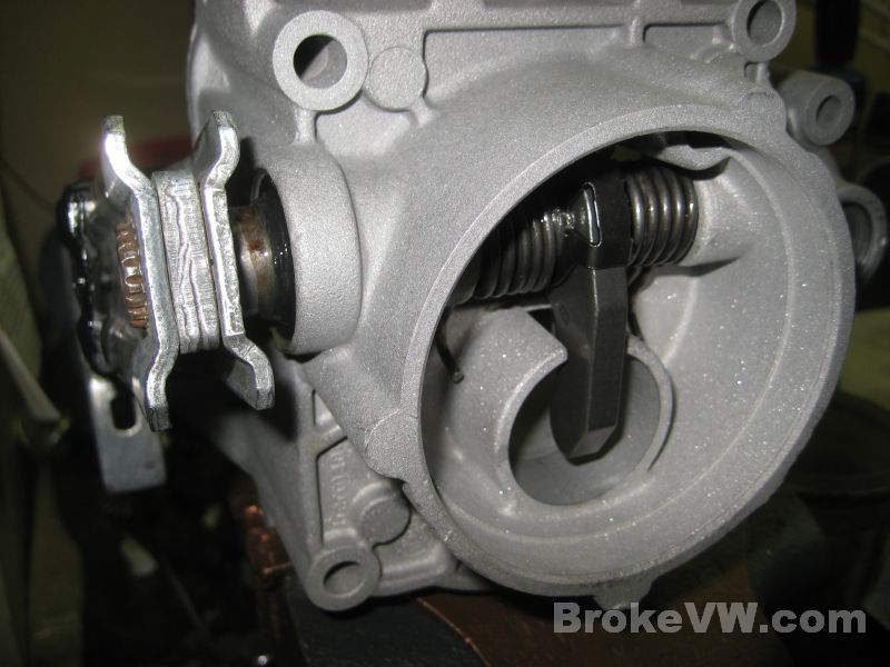
The release arm, spring and actuation finger are installed and secured with the spring clip...
The additional support bearing is installed...
Time to press the casing together. The gaskets surfaces are cleaned with a solvent and the VW sealant paste is applied, then it is pressed together...
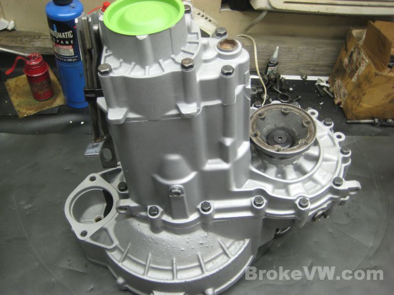
Bolted up and ready for the 5th gears...
Locking the 5th shift fork in place after adjustment. I made a tool out of an old flange seal, it protects the gasket surface while the lock plate is hammered into place...
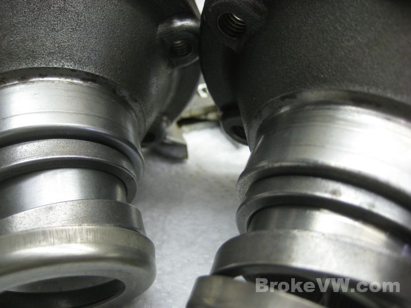
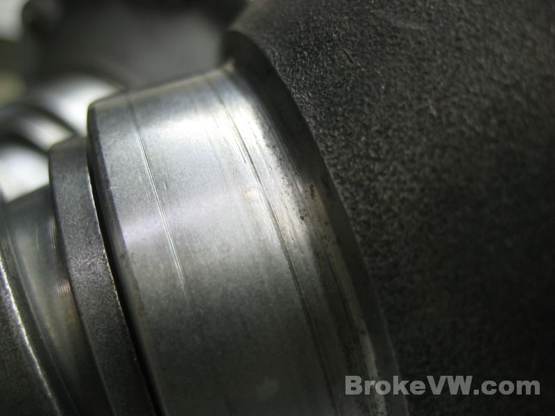
A couple pics of the flange seal surfaces, they are showing wear lines but they aren't grooved yet so they should be OK...
The starter bushing and install tool. I modified the tool by drilling a vent hole through it to make it easy to remove. The tool fully supports the bushing while it is installed to prevent distortion, and the vent hole prevents the tool from getting stuck via suction in the blind hole...
The pile of parts needing installed is getting smaller...
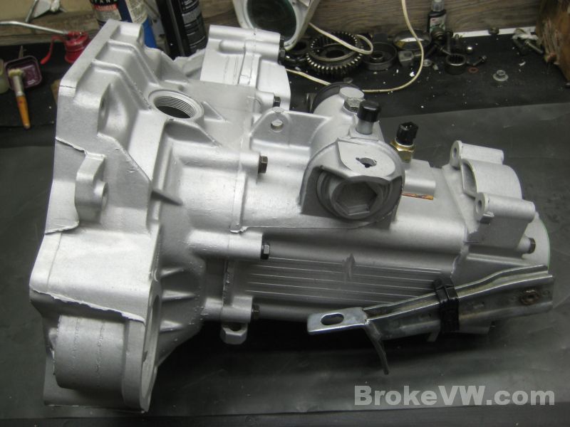
I still have to media blast the selector cover today... as you can see, it doesn't match the rest of the casing...
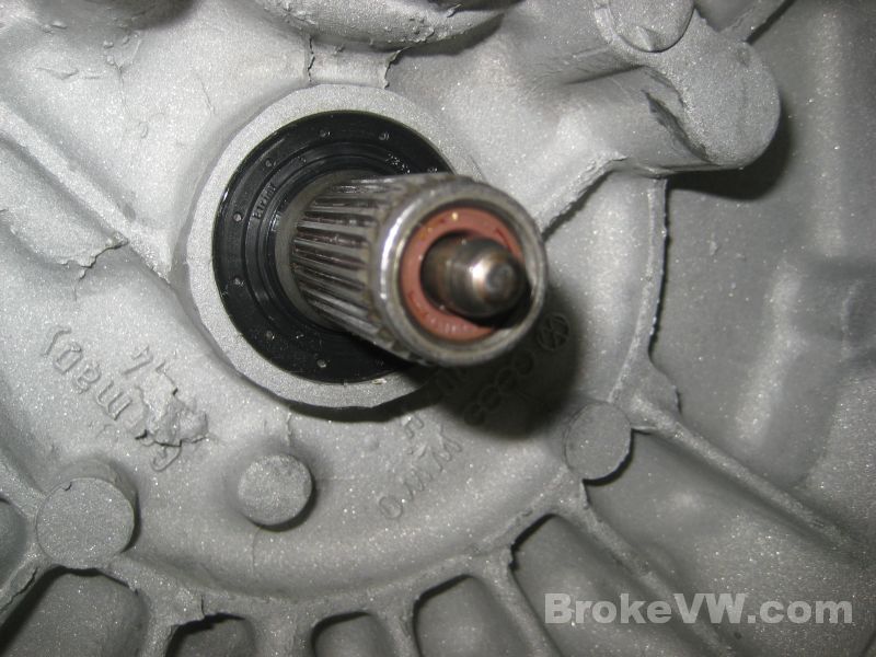
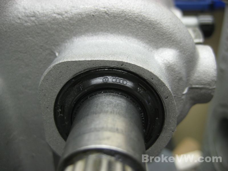
The old pushrod and a new input shaft seal are installed...
At this point it is a matter of waiting for the 80% kit to arrive in the mail tomorrow, and I should have it completed by tomorrow evening.
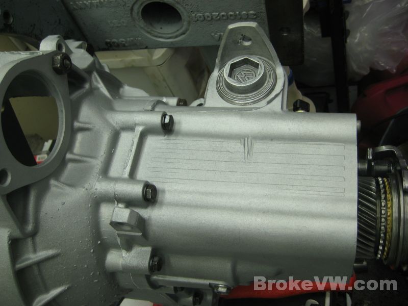
I installed the remaming parts and have blasted the selector cover, the only thing left to do is install the 80% kit and the flanges and get the packaging made for it.
The selector shaft seal installed...
VW sealant paste to get the 5th housing installed...
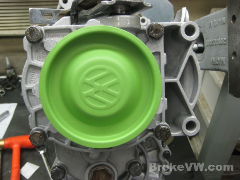
A VW green end cap completes the 5th housing...
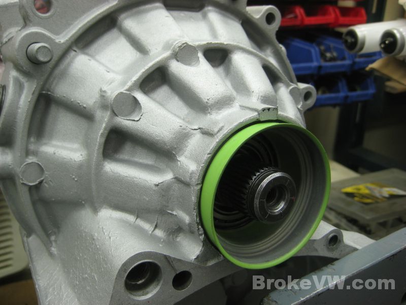
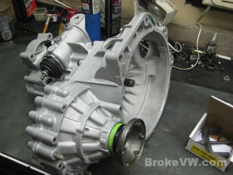
The green seal sleeve is installed and it's just the flanges left now...
The selector cover now matches the rest of the casing...
Update 04/26/13
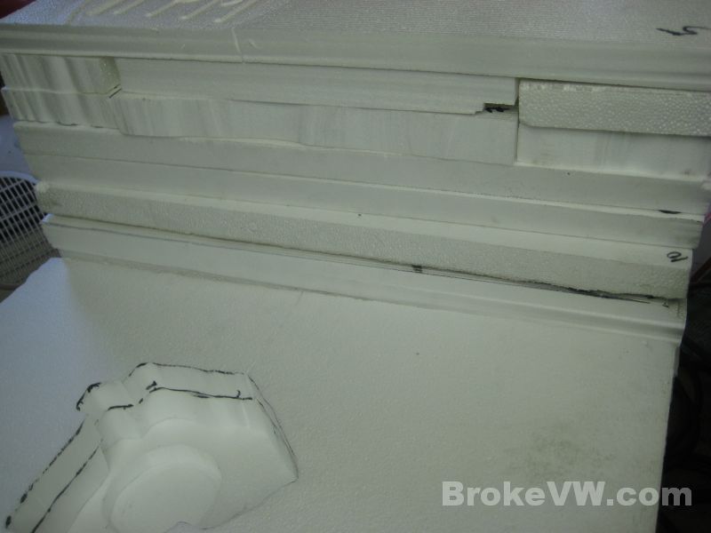
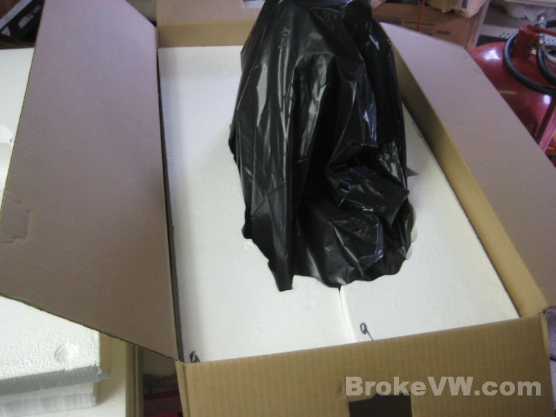
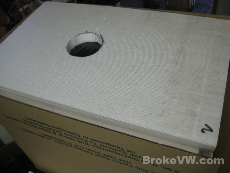
Waiting on the 80% kit to arrive I've cut the foam sheeting for your trans package. The trans will sit on the face of the bellhousing, the passenger flange fitting into a hole in the bottom, then the layers are built up around the trans until it is covering the 5th housing and green end cap....
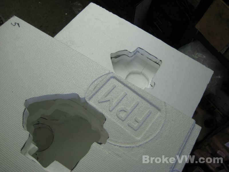
I use a hot wire cutter I made by stringing a piece of hobby wire from the ceiling to the work bench, an old 12V charger heats the wire. I slide one lead up and down the wire to adjust the "working length" of the wire which adjusts how hot it gets, the other lead stays clipped at the bottom of the wire...
Update 04/28/13
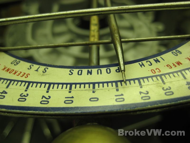
I have the 80% kit installed and the trans packaged up, it is a very solid 17x26x22 package that is showing 81 lbs on my scales but that seems a little light. You can easily stand on any side of the box without hurting it so it should make the trip no problem.
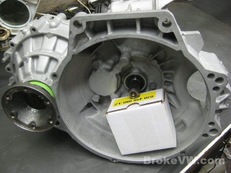
Your 80% kit....
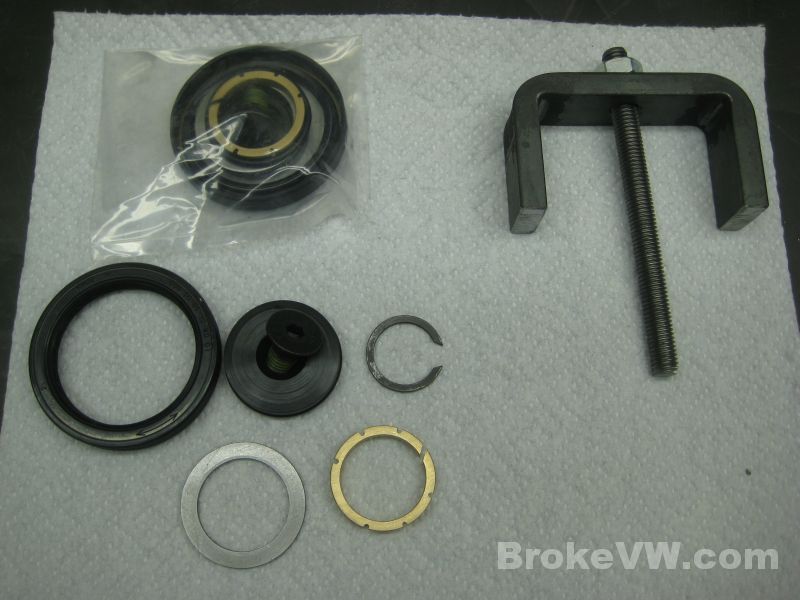
The drivers side bronze thrust washer and shim installed with a new greased seal...
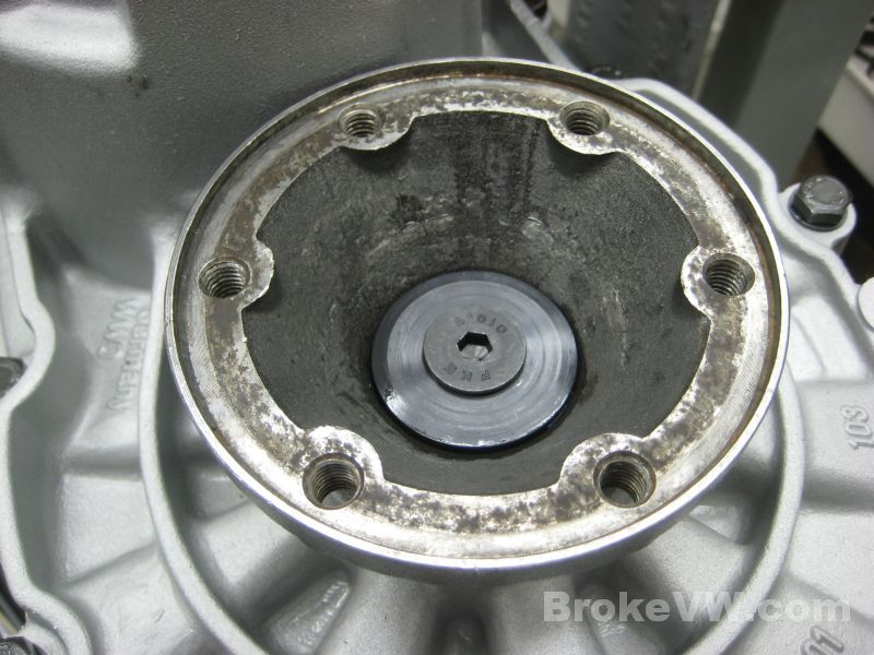
The circlip installed...
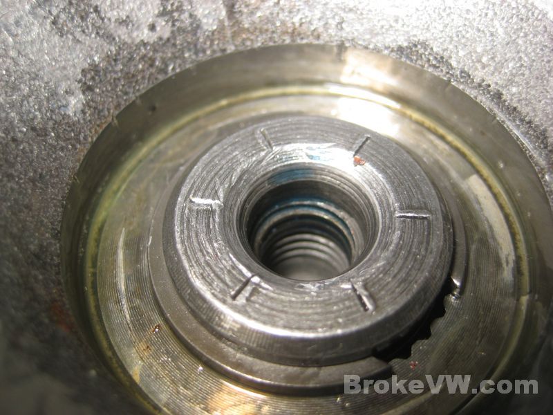
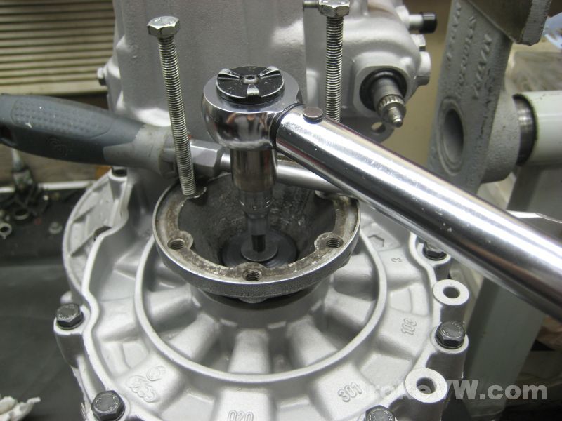
Tightening the center steel cap bolt to 33 ft-lbs...
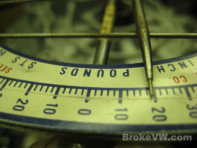
When both sides were done I checked the break torque on the bench and it is pretty tight at 95 ft-lbs but this will decrease as the parts wear in...
The passenger side circlip wouldn't seat fully. Between the fresh parts in the diff and the 2.3mm snap rings used on the other side of the cross shaft, there simply was no room to get the circlip into the groove to secure the flange. I thinned the 80% shim down a few thousandths at a time until a circlip was able to fit into the groove. I used old circlips I found in the scrap bin to use as a feeler gauge until one fit, then I replaced it with a new circlip for the final installation....
All done and built...
I've put the 80% kit box with the new flange tool and your flange concave washers (to be used if the kit is ever removed) in the bellhousing cavity...
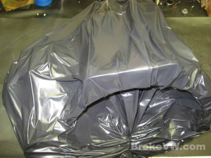
The trans is covered with a garbage bag and the air pulled out....
About half packed, I started with sheet 15 I think so there are 7 sheets in the box here and 8 to go on top...
Nearly packed....
I finished the package by slipping another box over this box and taping it all up, it's very solid and there isn't any movement inside so it should be fine.