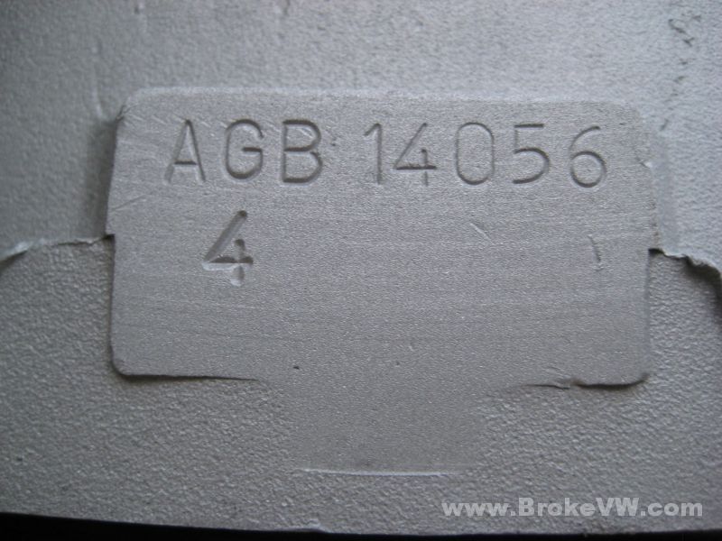
AGB 020
4.81 Hoer R&P
Gripper LSD
Matt Bushore - Ann Arbor MI - July 2007
Returned 6/17/09 - Done 7/02/09
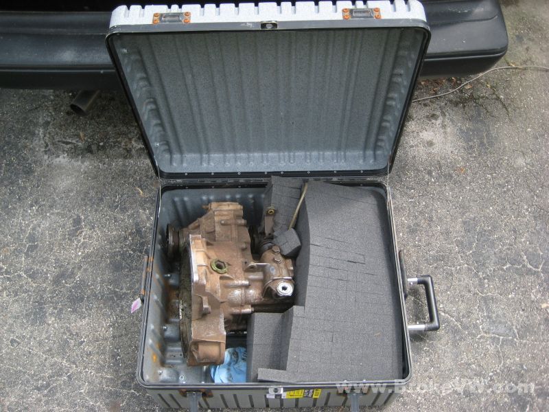
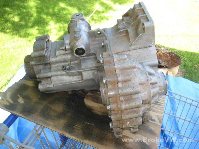
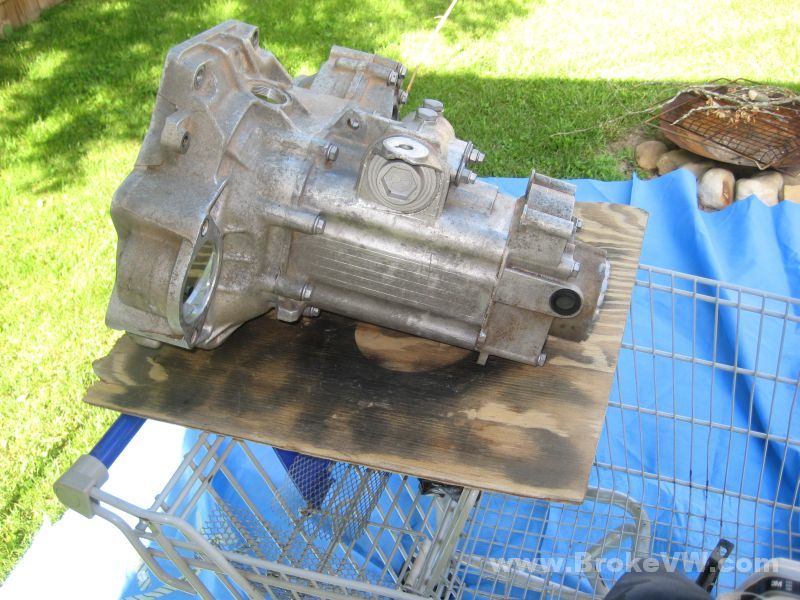
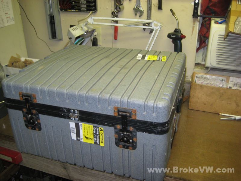
Nice case! The UPS man even liked it!
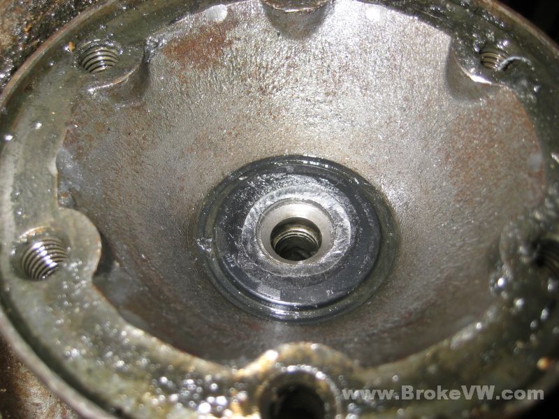
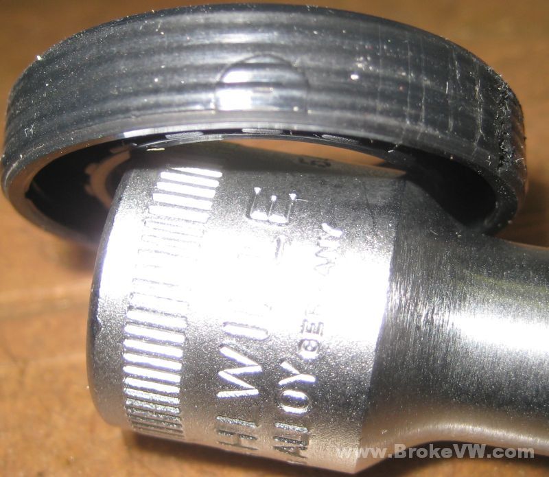
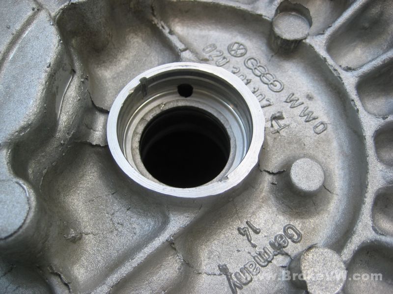
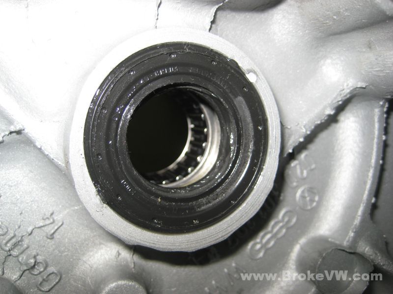
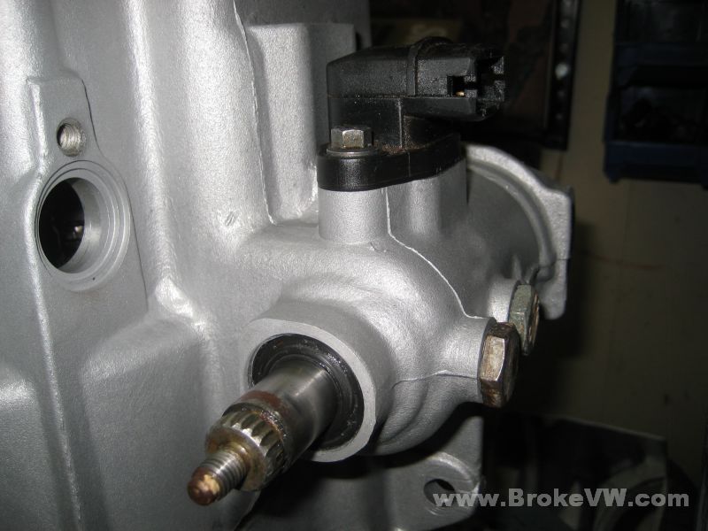
After getting it up on the bench, I had a look at the drivers side flange center seal, and could see the axle had machined through the cap, I assume when it failed on you?
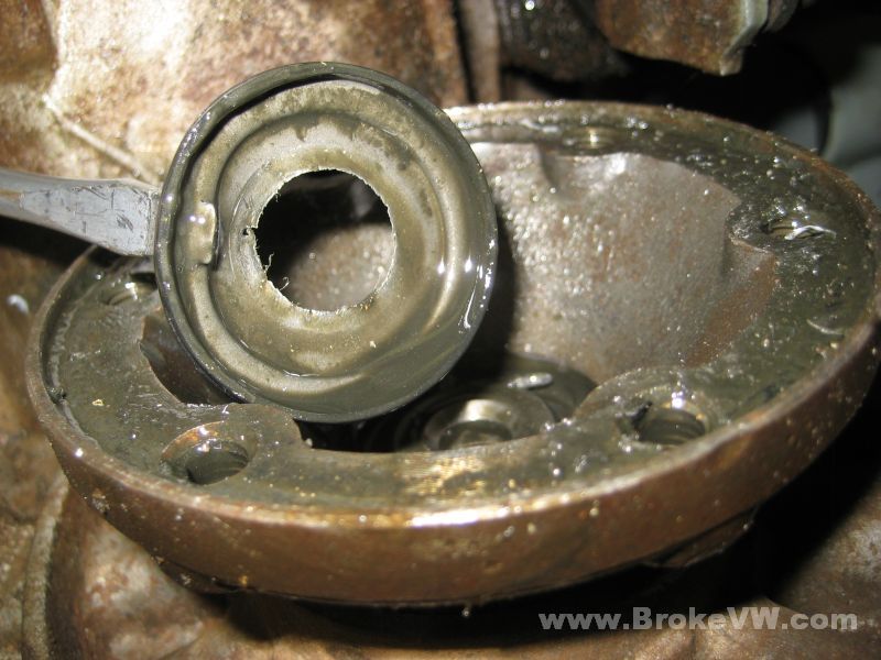
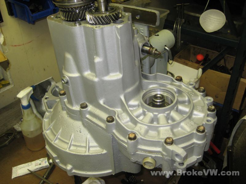
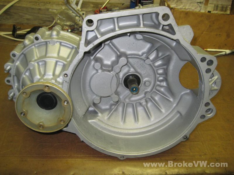
The 5th housing removed...
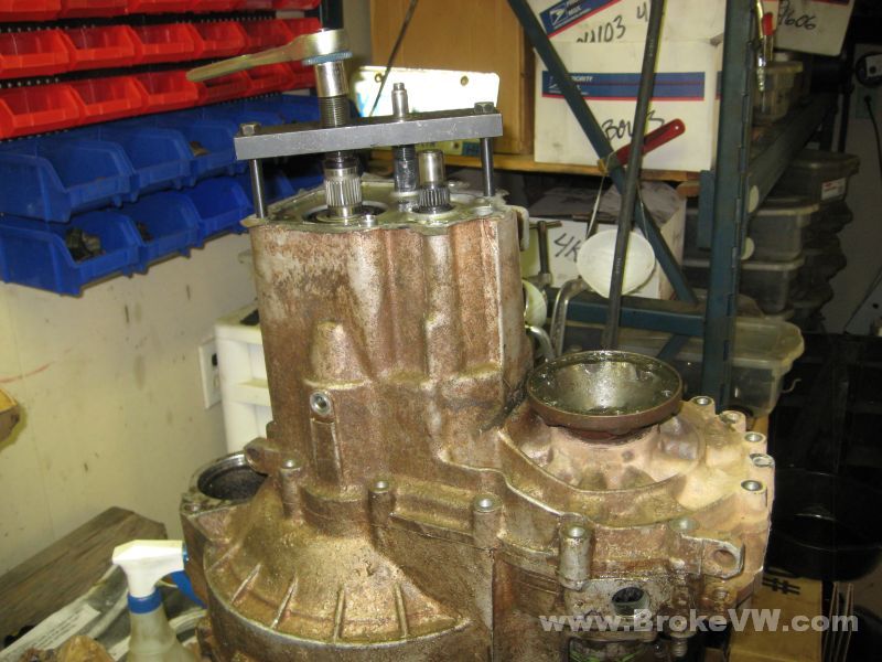
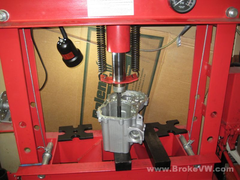
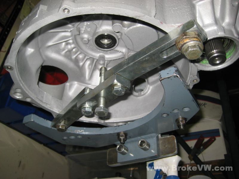
The case splitting tool mounted up, I just need to pop the drivers flange off and the case can be split...
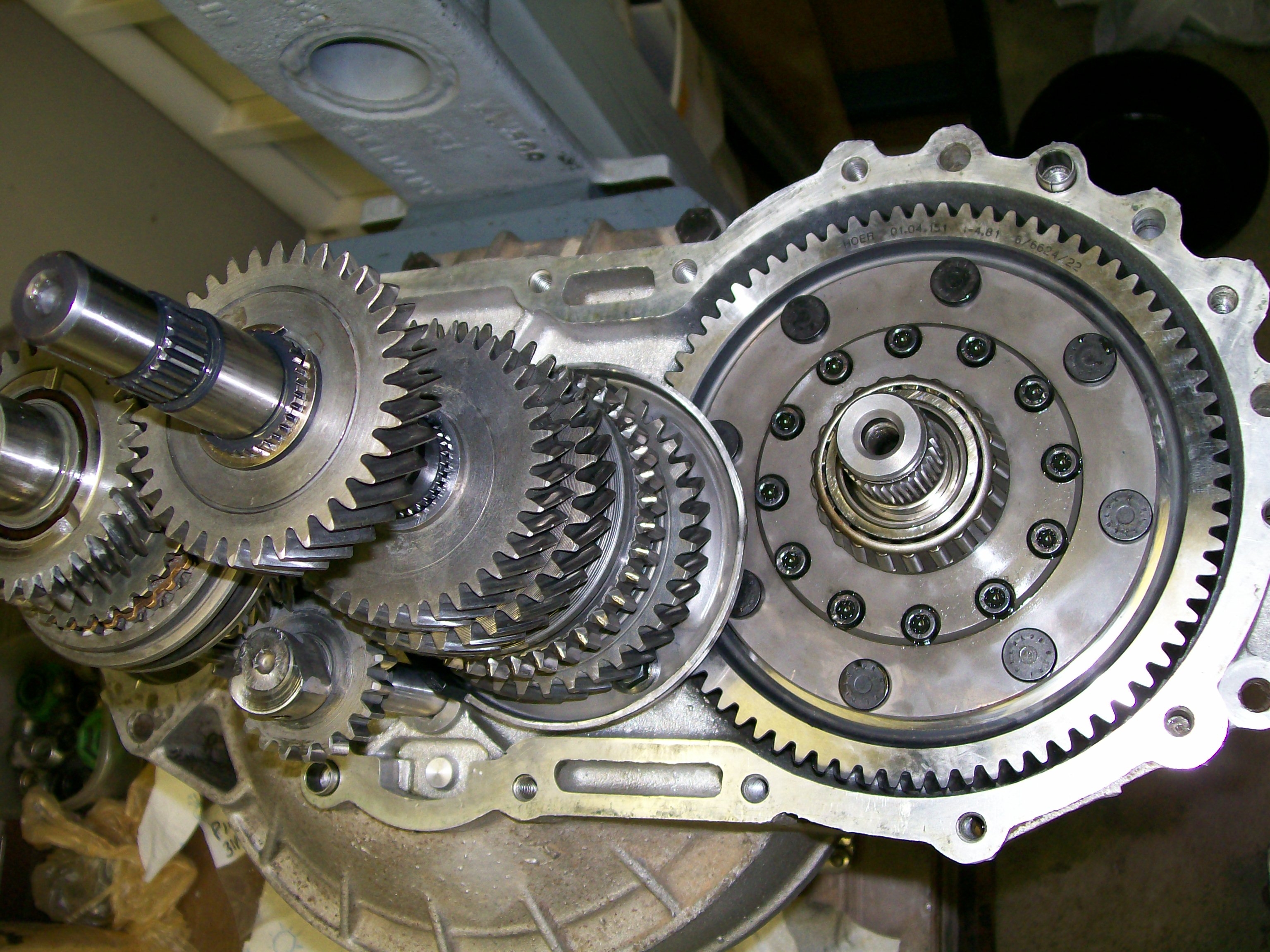
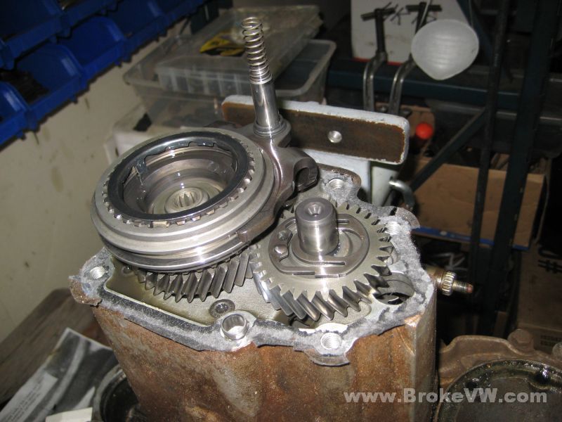
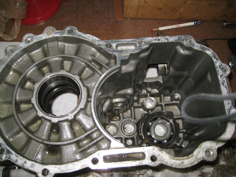
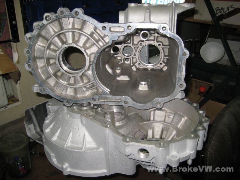
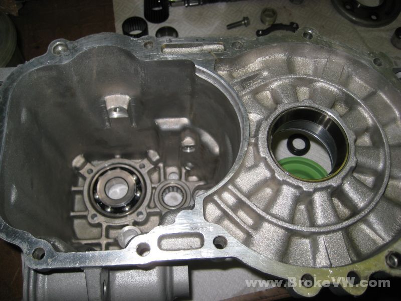
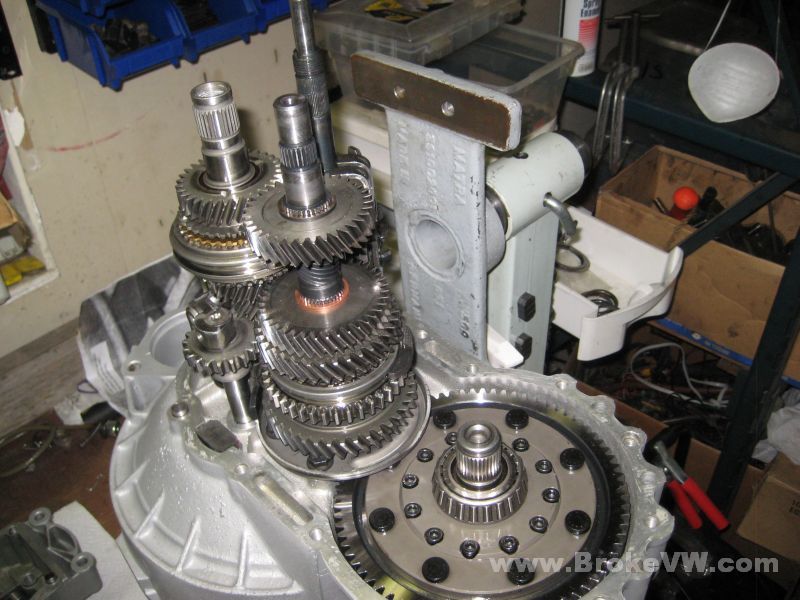
Opened up, and it looks pretty good, not too dirty inside...
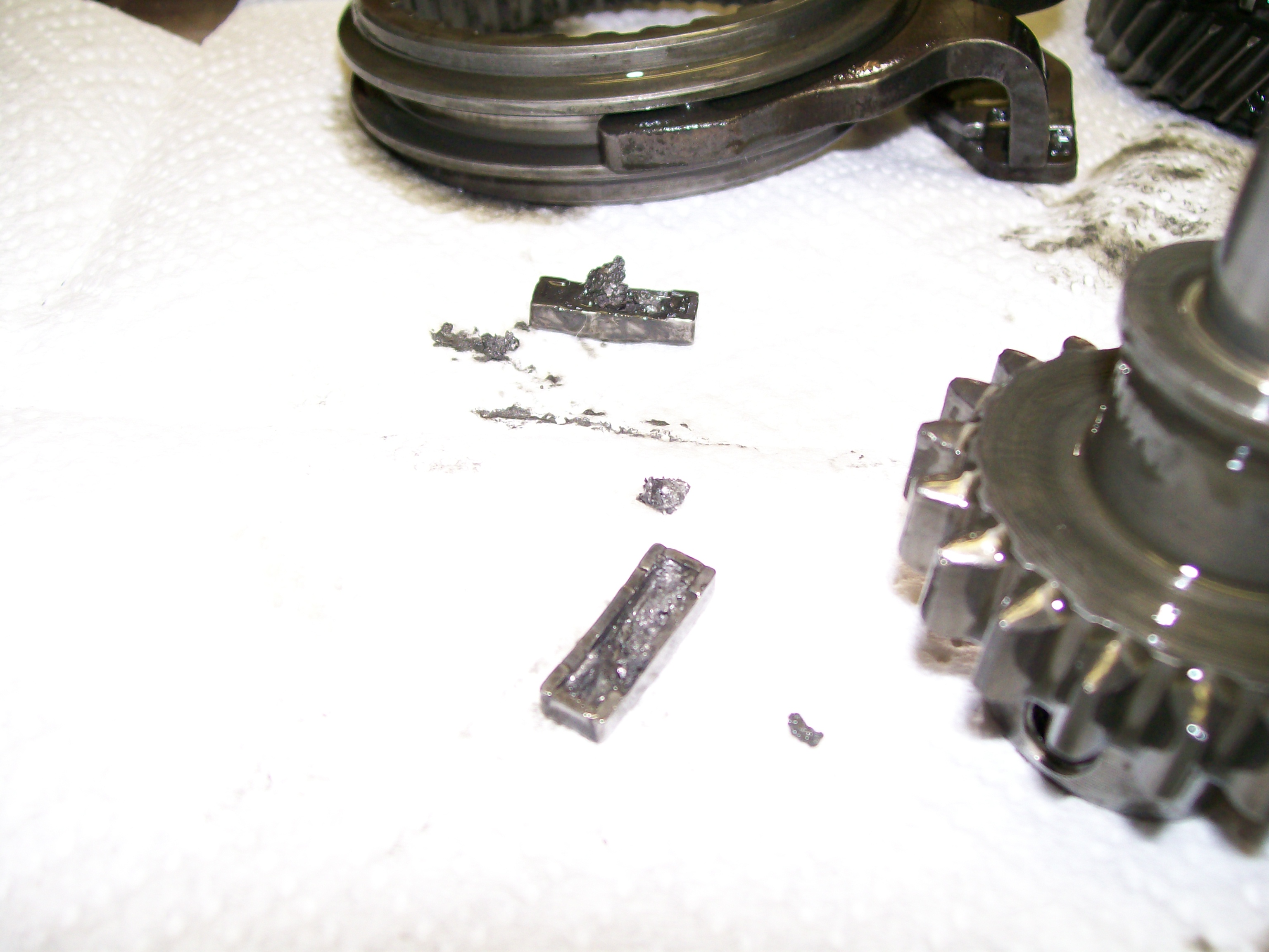
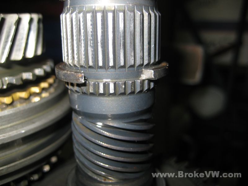
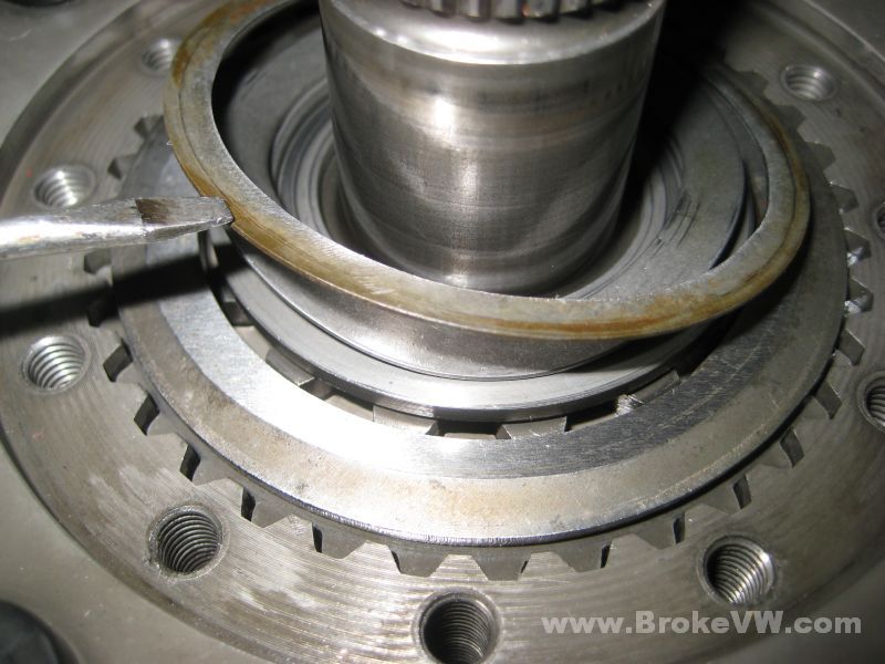
The circlip shoved out of the groove by 3rd gear, I'll replace it with a 2.9mm and see how that fits...
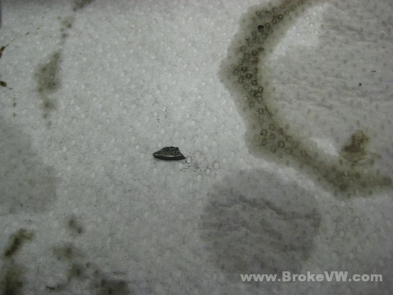
The unexplained 4th gear circlip that has a broken tip...
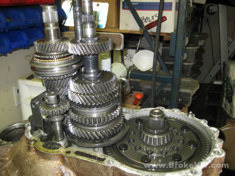
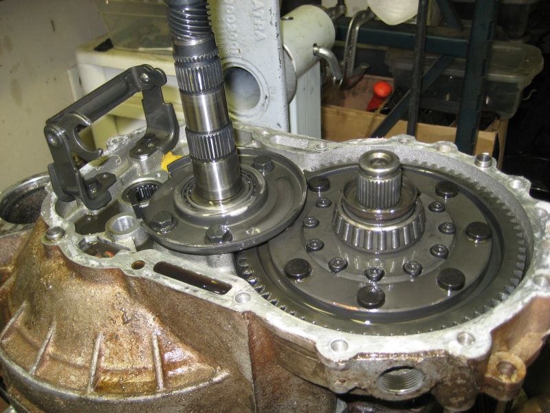
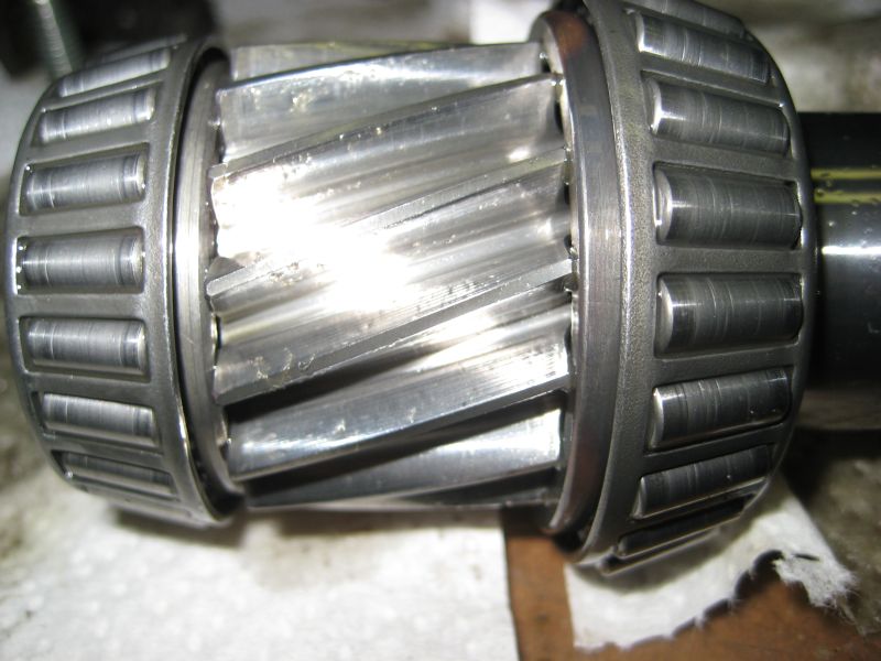
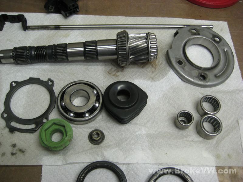
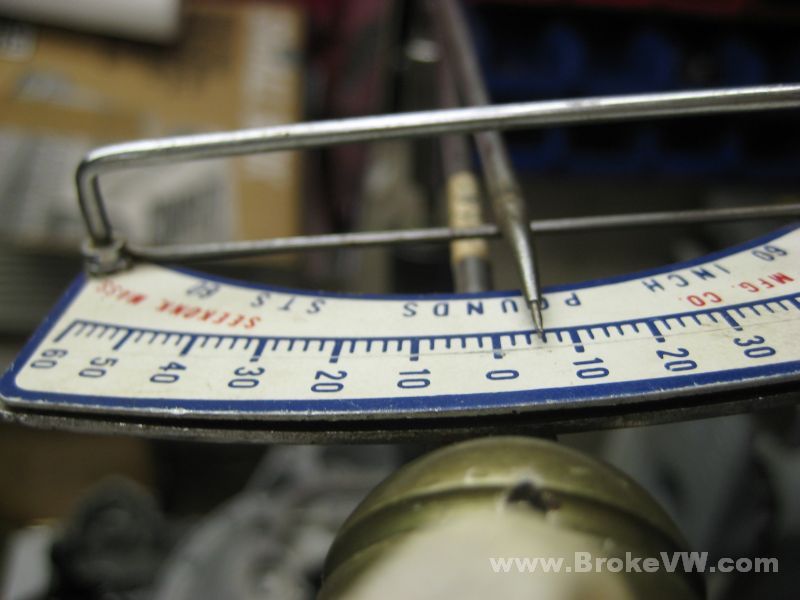
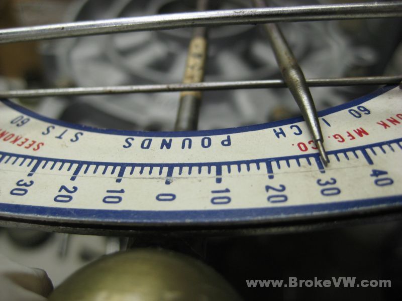
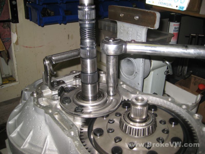
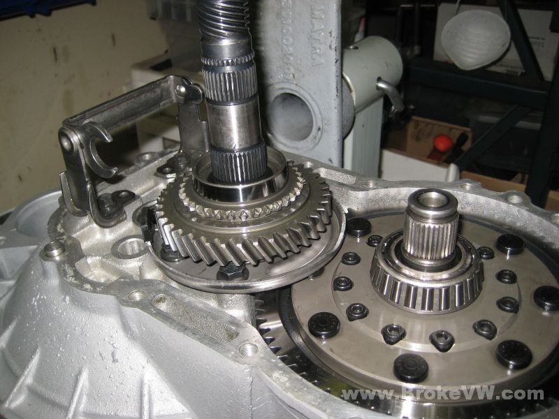
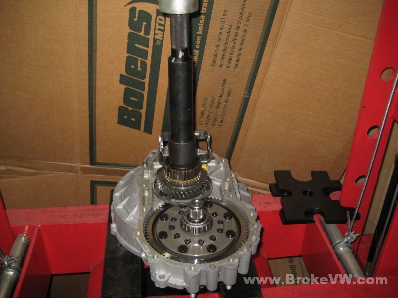
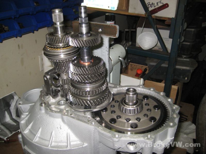
The input shaft removed and the output shaft stripped. I attempted to check the bearing preload, but frankly, the spec is 3 in-lbs, which is so light, my in-lb meters are hard to read that low, but it was bouncing between the 2 and 4 marks, so it seems to be OK and still in spec, which is good.
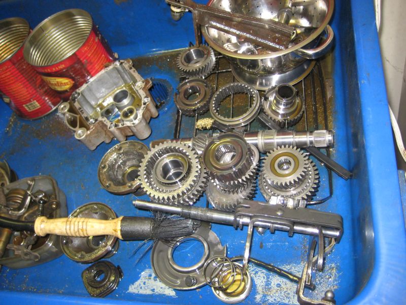
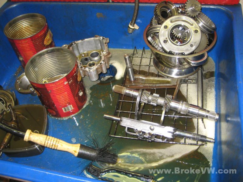
Parts in the parts washer to get cleaned up. I'll figure something out with the case... the seals and bearing races and so on will stay in the case, so I'll need a way to clean the case without removing the seals if possible...
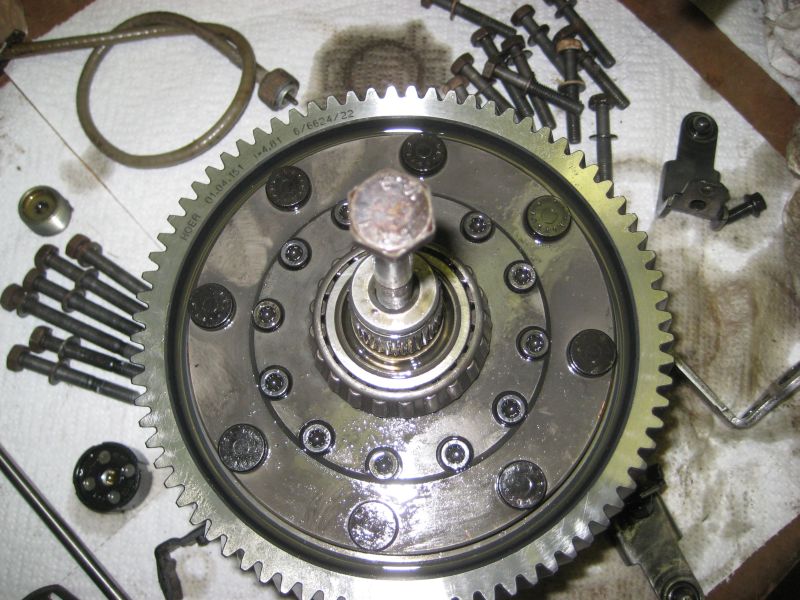
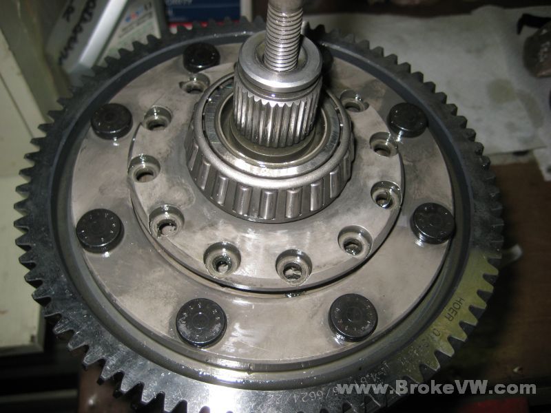
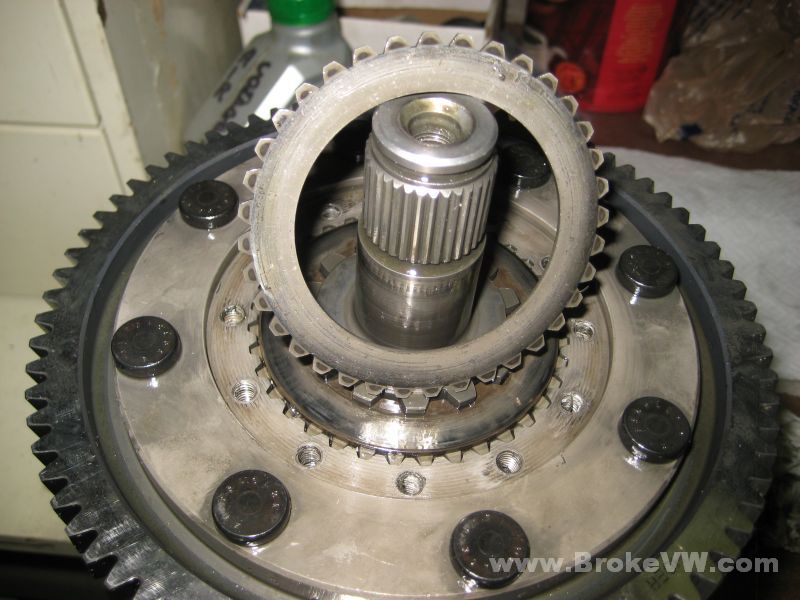
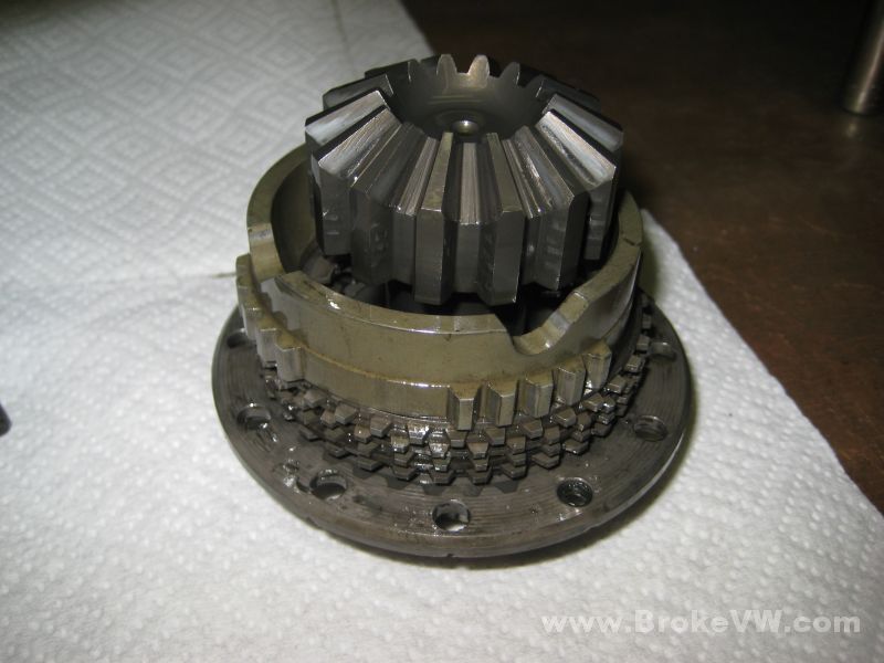
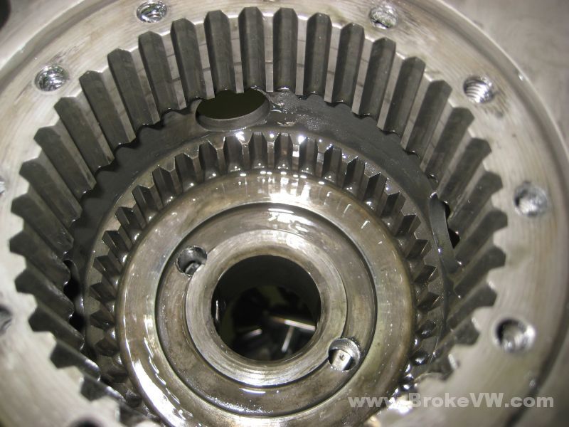
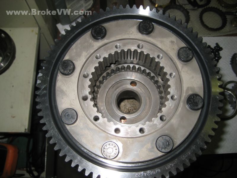
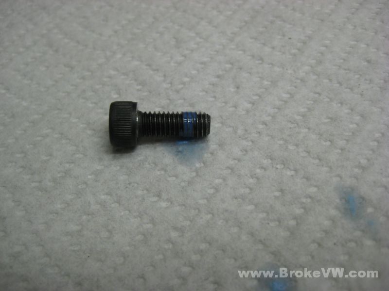
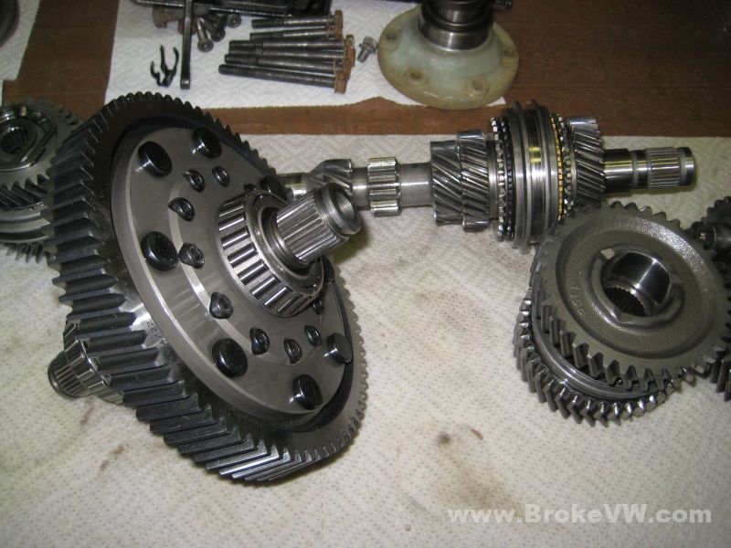
The LSD lifted out (the bolt threaded in gives me something to grab with oily gloves)...
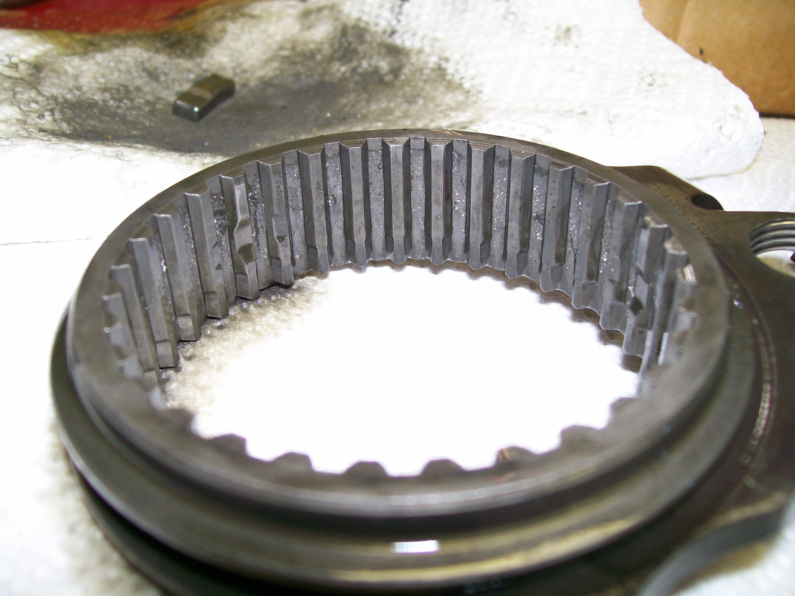
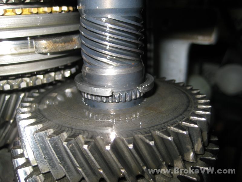
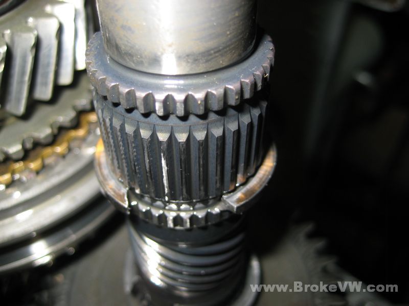
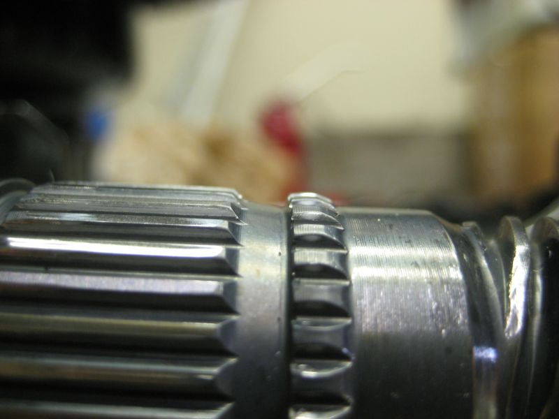
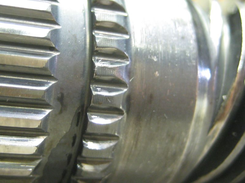
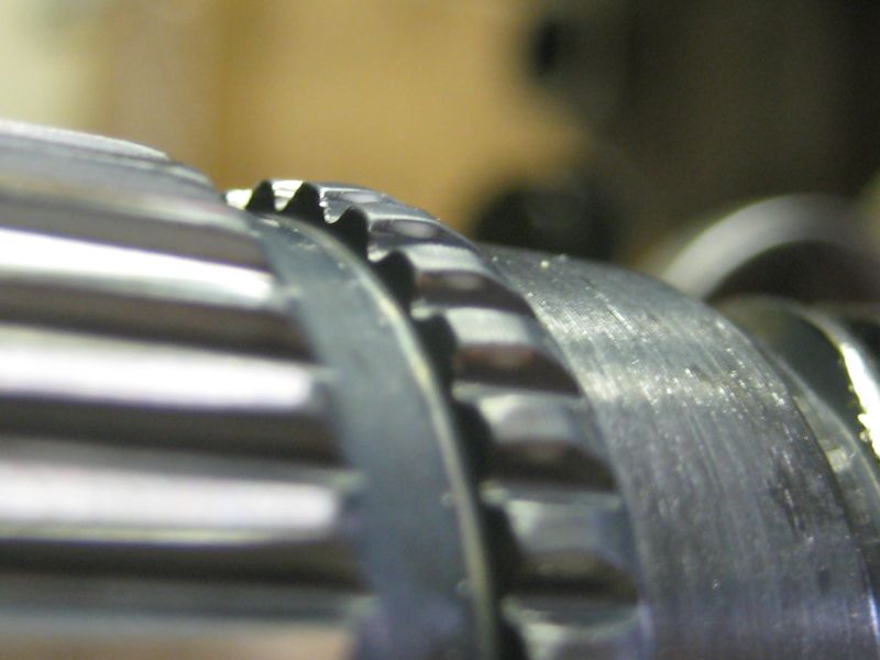
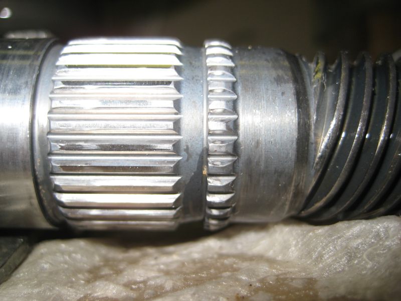
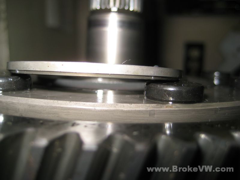
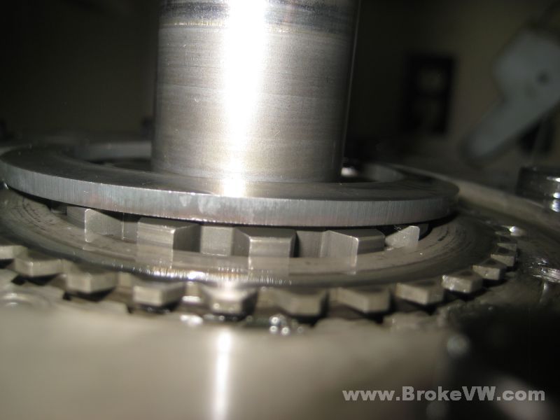
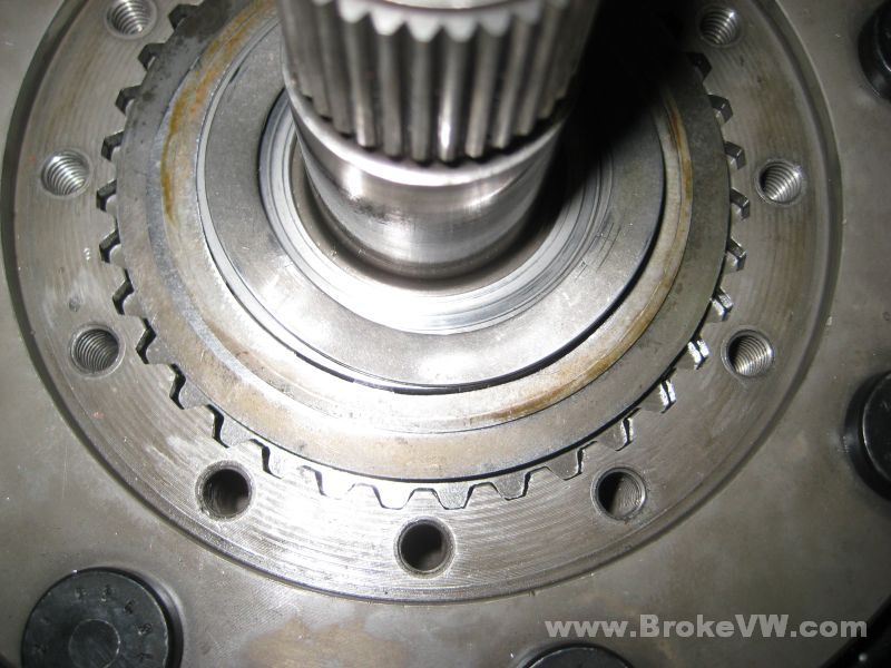
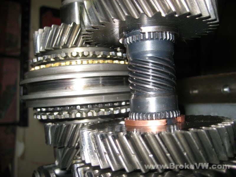
Some close shots of the groove for the 3rd gear circlip... I don't see any broken splines or anything, and the teeth still look sharp, so I'll try a 2.9mm circlip and see how that does....
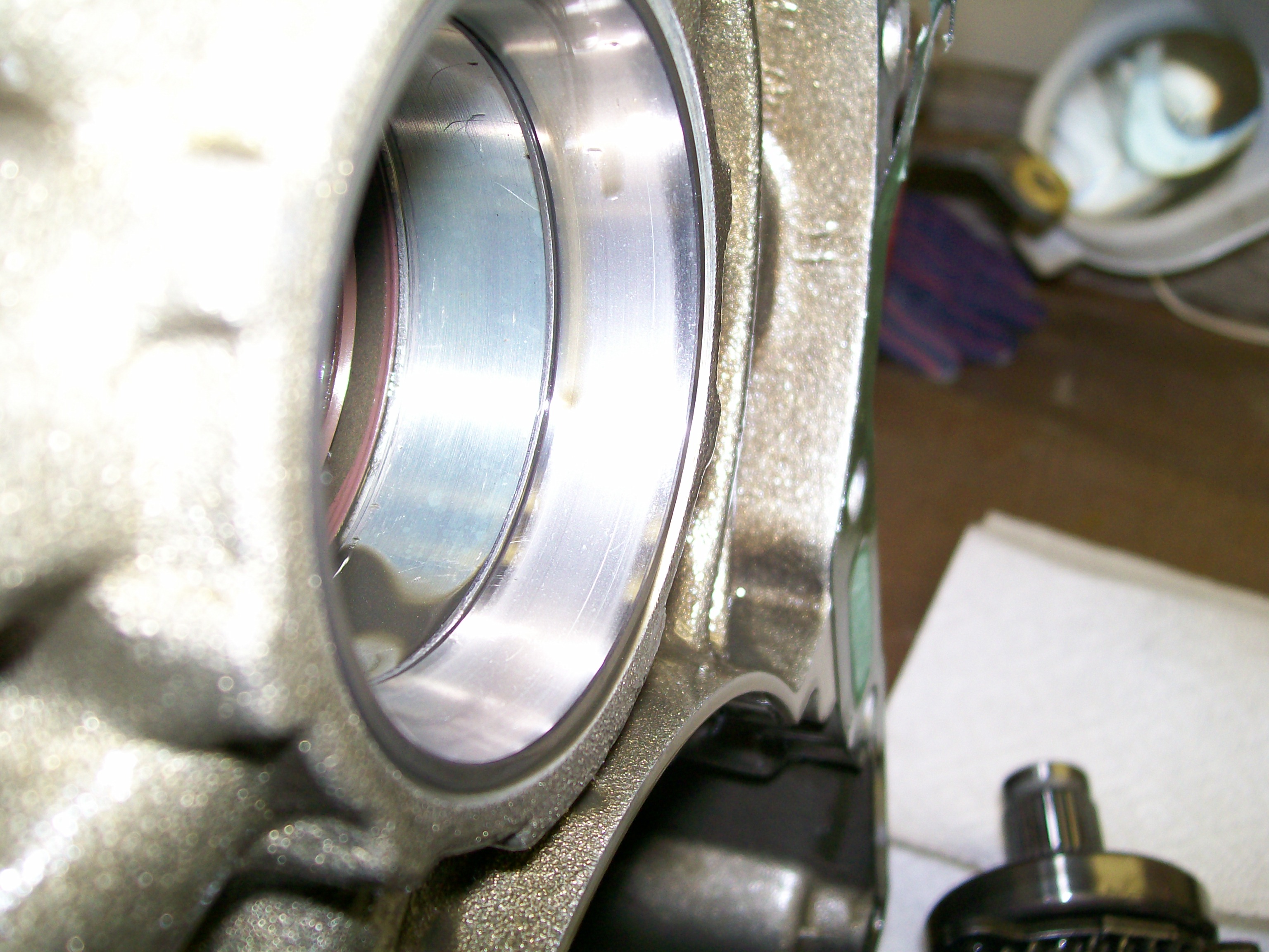
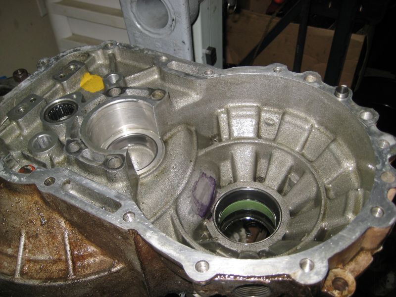
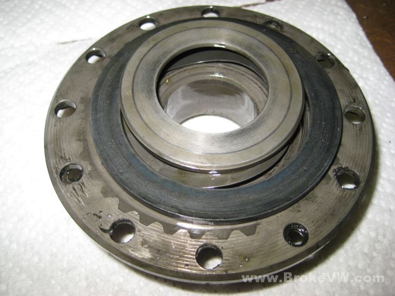
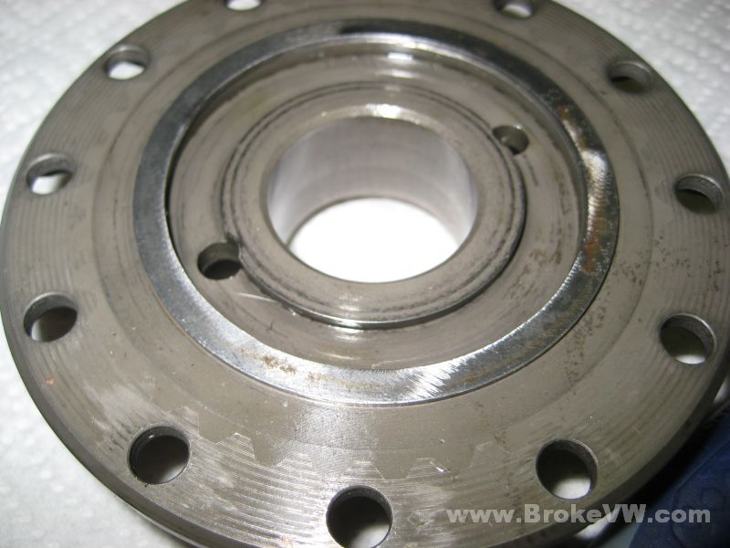
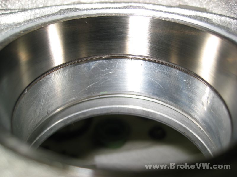
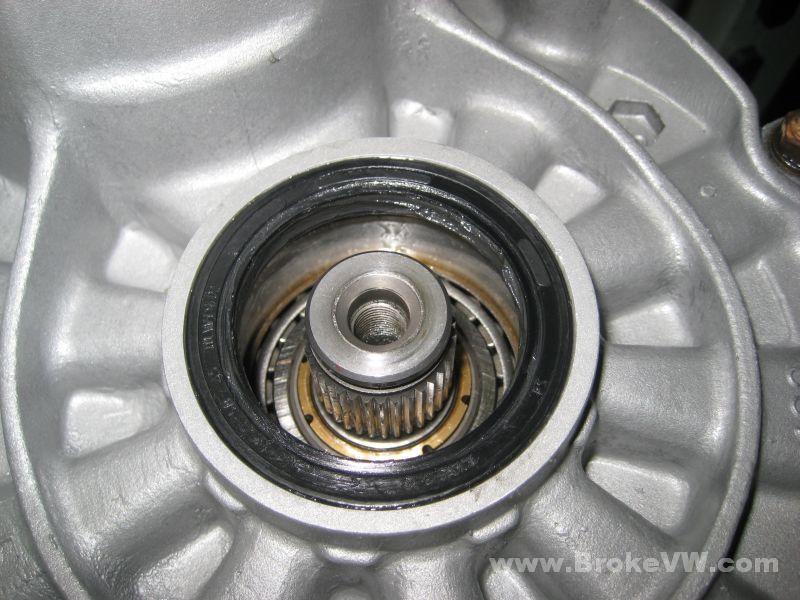
The drivers side diff bearing race... it looks more worn than the passenger side bearing, but I'm not sure if it is worn enough to warrant replacement yet...
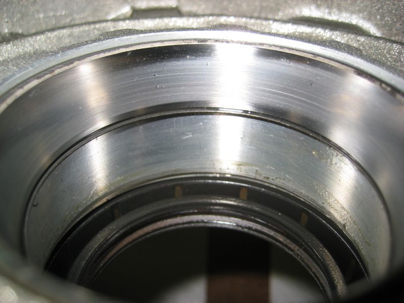
The passenger side bearing race looks better, but I wouldn't say either one of them are shot or anything...
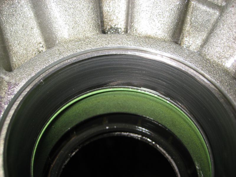
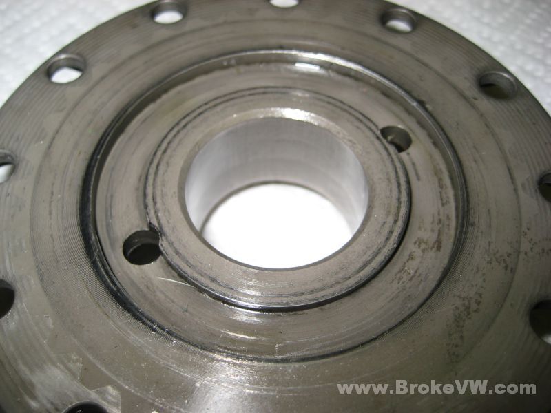
The output shaft small bearing race looks OK as well, and it is the one that usually takes the most abuse due to the size...
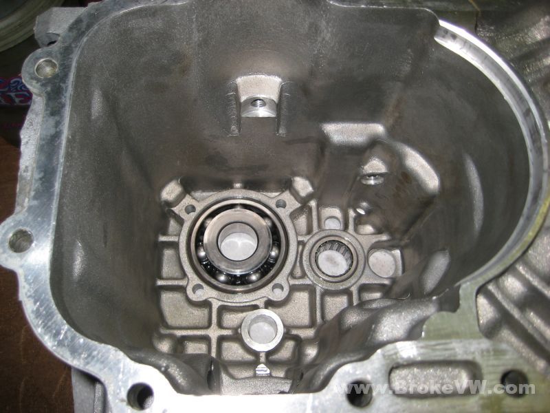
A couple pics showing the inside of the case, it doesn't look too bad after a couple years. I see the case needed grinding to fit the LSD, which is surprising to me, as it is a 16V case, so it is at least 1987 or newer, and I thought the cases had the room by 1987... I've had to grind some early 1984 and 1985 cases... I guess up to 1987 the cases still need work to fit the LSD...
Update 6/19/09
Parts cleaned and dripping the excess kerosene off before being rinsed, dried, and oiled...
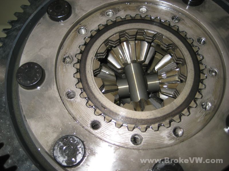
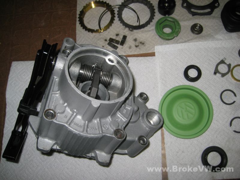
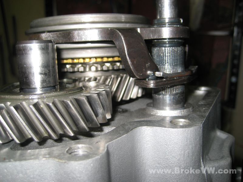
I removed the LSD bolts evenly allowing the cover to lift off...
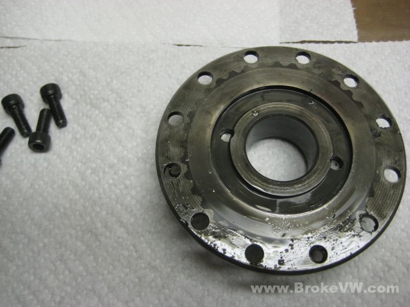
After the cover is a wavy washer, then a thrust washer, then a bellville washer...
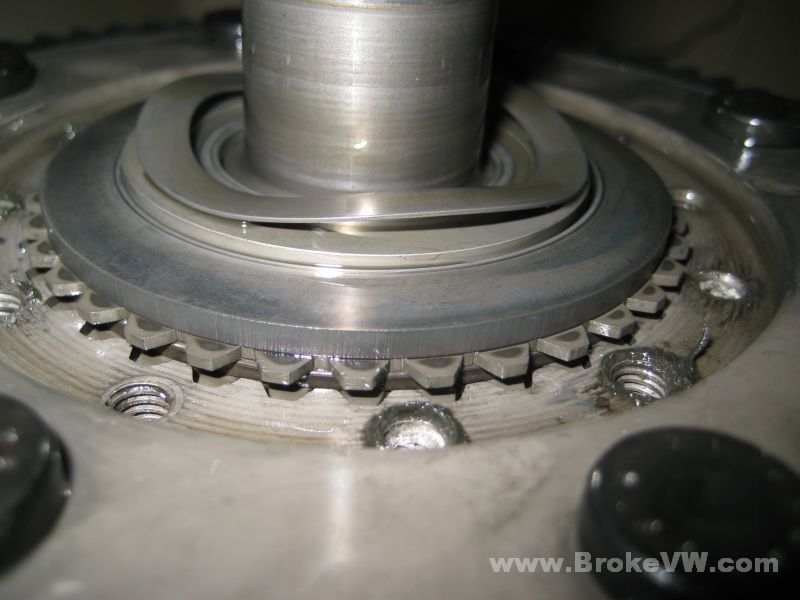
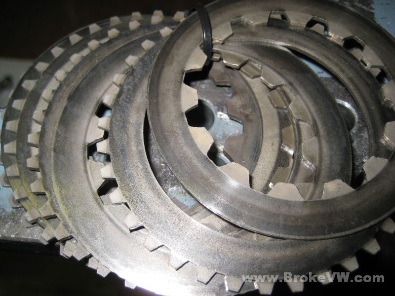
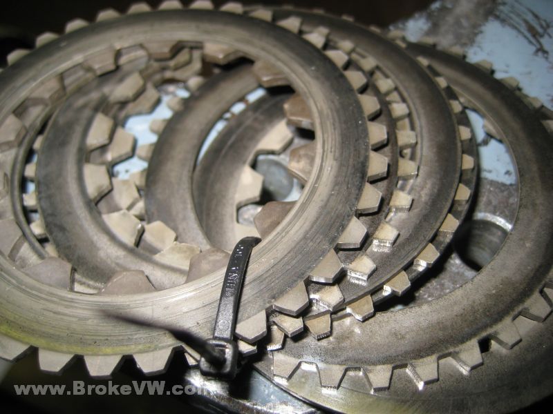
After that it is the clutch discs, you have 4 int. splined and 4 ext. splined on the ring gear side...
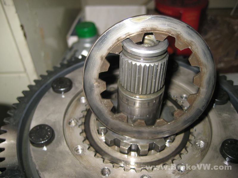
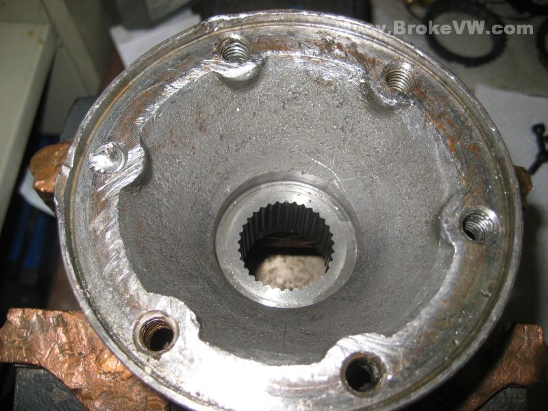
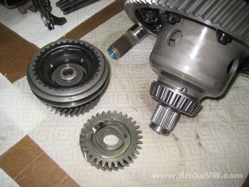
The stub axle and side gear is one piece...
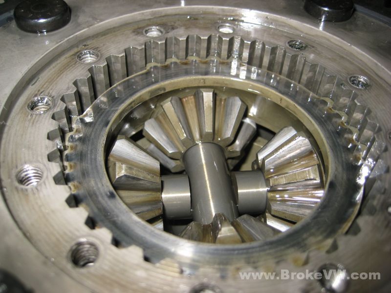
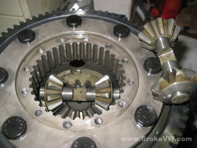
The ring gear side clutch discs and the spider gears and cross shafts down there...
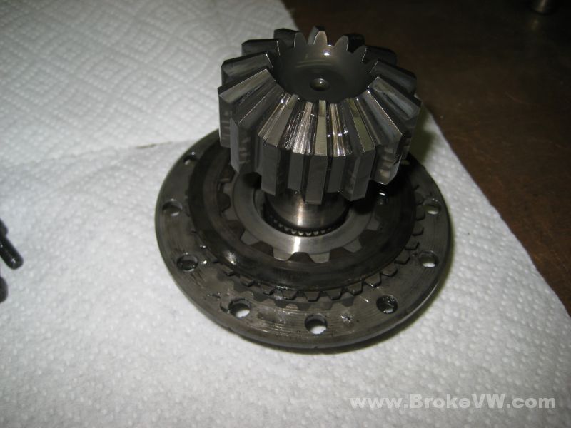
The side gear driver...
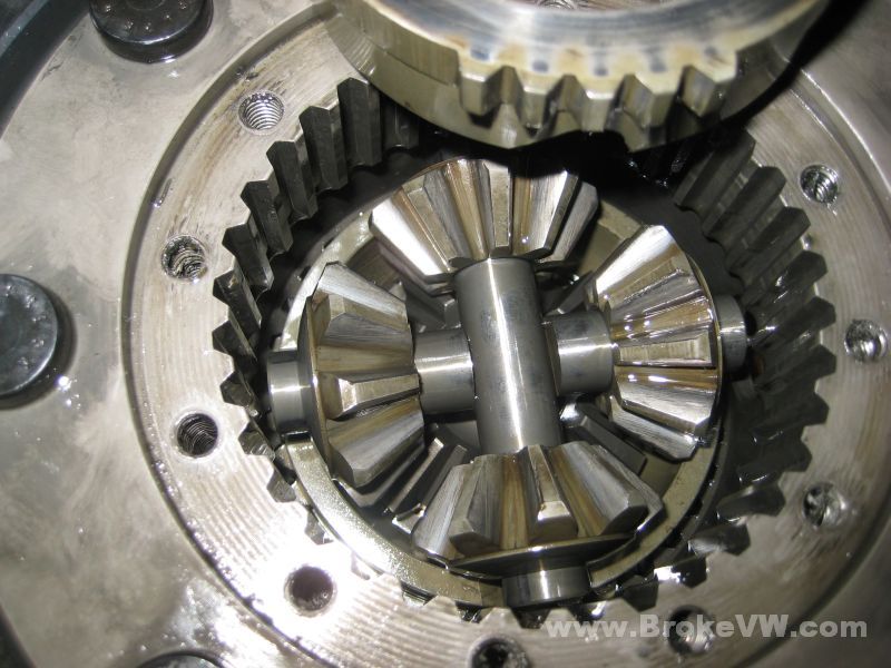
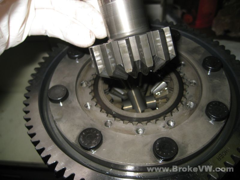
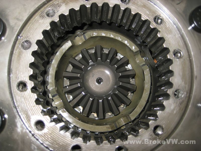
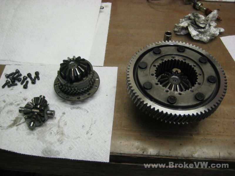
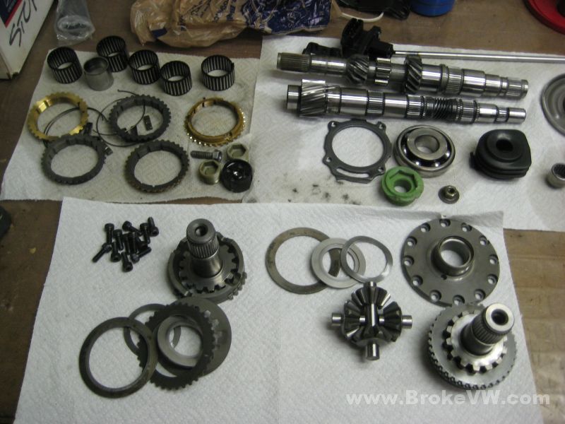
The spider gears and shafts lifted out. They'll all go back in the same spot that they came out of...
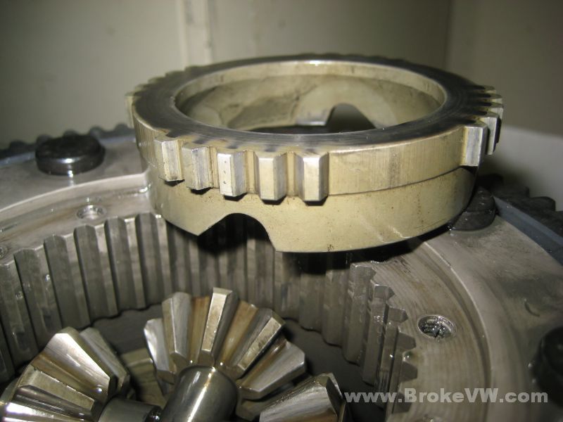
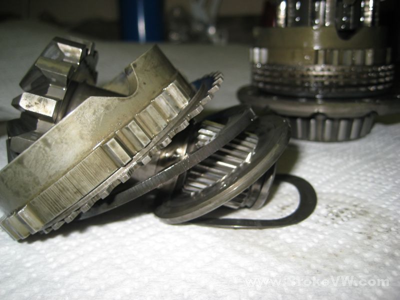
The cage side parts, the side gear driver, the side gear, and the clutch discs...
The cage side parts... you only have 2 discs on this side, one int. and one ext. disc...
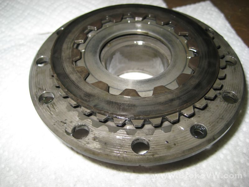
The empty LSD cage...
That's it, I'll get them cleaned and when the new discs arrive I'll get it built. I plan to talk to Gripper about adjustments and so on...
Update 6/23/09
Testing the preload, I'm still waiting to hear from the UK... but here is what I have found so far:
If I secure the ring gear in the vise and spin the output shafts,
I get different readings for each side:
Spinning the drivers output shaft - 95-100 ft-lbs (CCW 90)
Spinning the passenger output shaft - 145-150 ft-lbs (CCW - high, it rolled the
diff out of the vise, probably around 135-140)
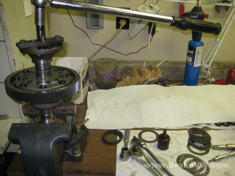
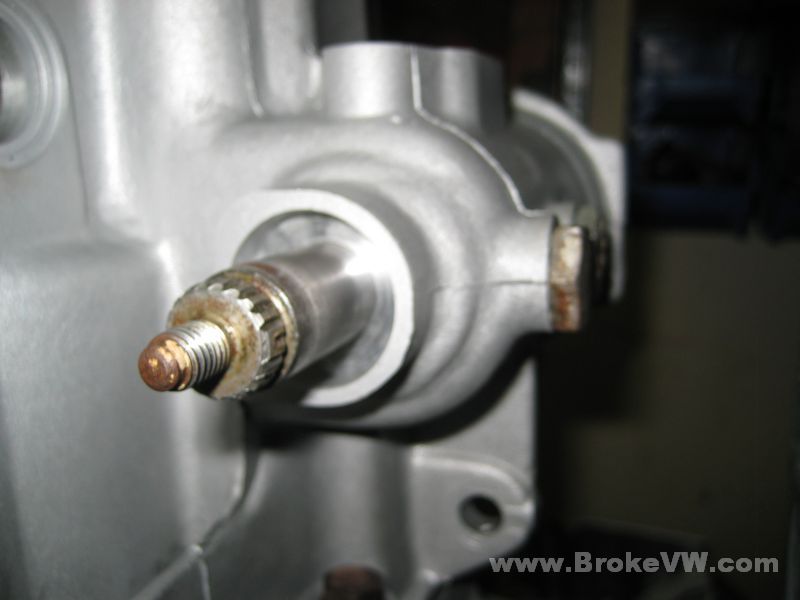
If I secure one output shaft in a vise, the readings are also different for each
side:
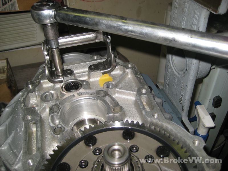
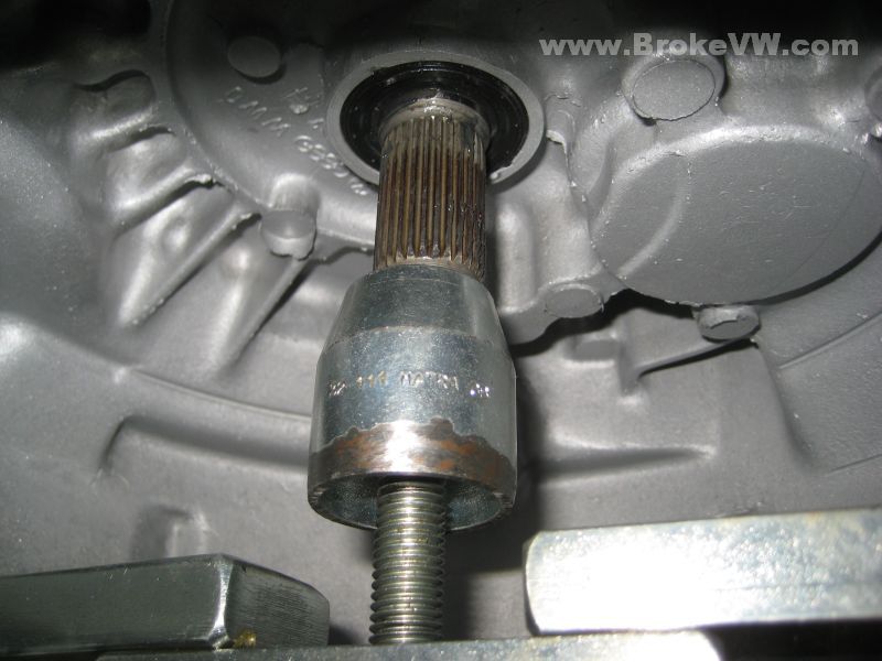
Spinning the drivers output shaft (as shown in the pic below) - 55 ft-lbs (CCW
50)
Spinning the passenger output shaft - 100 ft-lbs (CCW 90)
Once I hear from the UK about the preload results, I'll clean everything up again (it's clean, just a little dirty from working with it and pulling the clutch discs in and out over and over), put it back together, and use locking compound on the bolts.
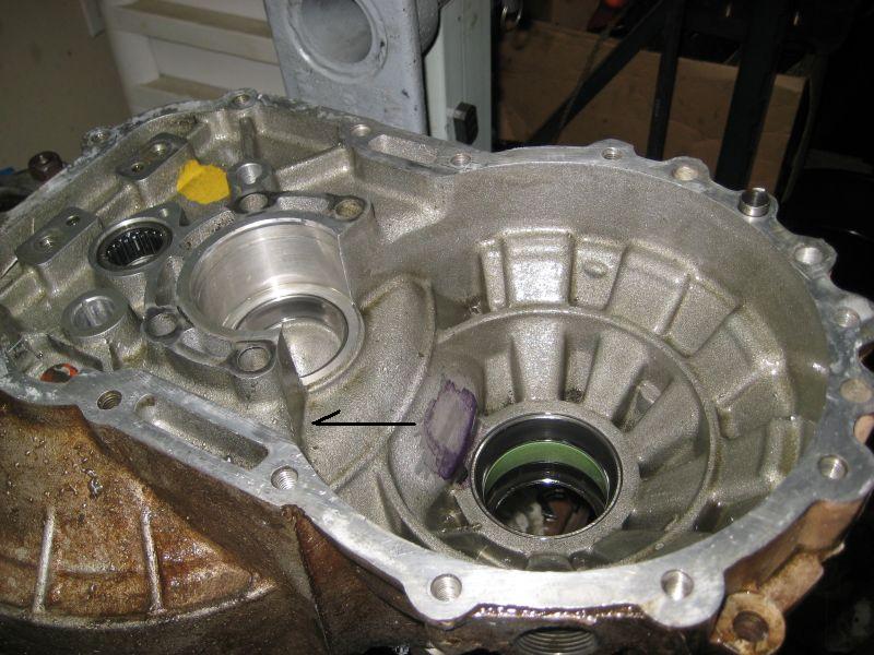
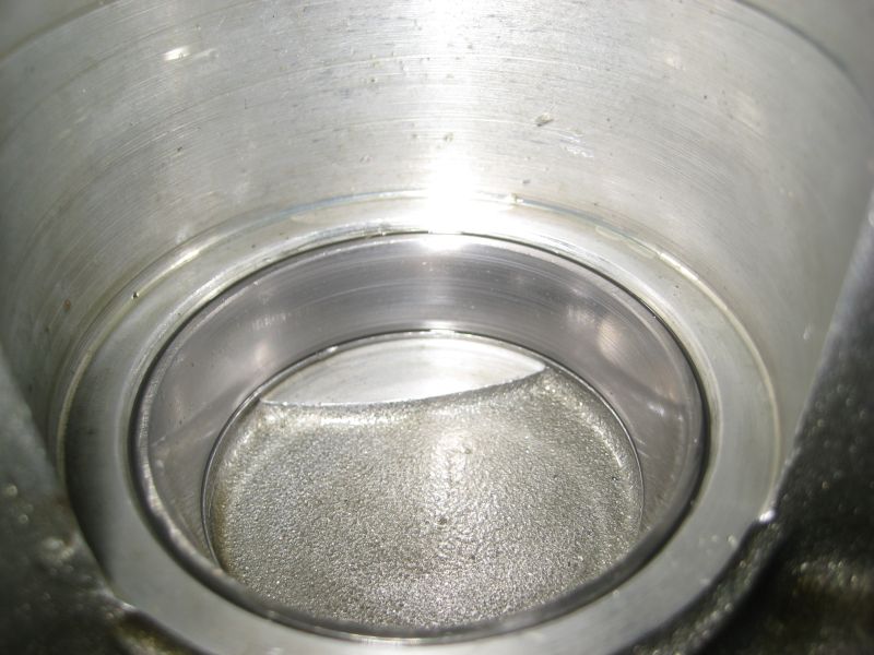
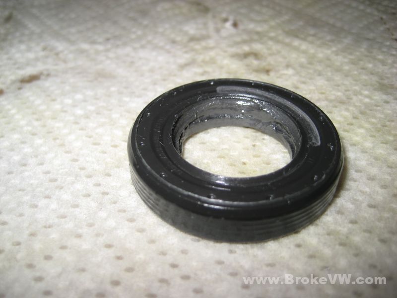
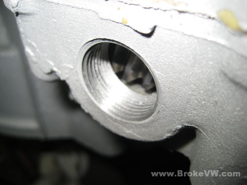
The input shaft seal, you can see where it was partially covering the oil feed hole, as it was pressed in too deeply into the case. There is also a jagged line in the seal (far right in the pic), it was caused by previous damage to the case. Someone has really dug into the case trying to remove an old seal, and has damaged it, which is leaving the mark on the seal.
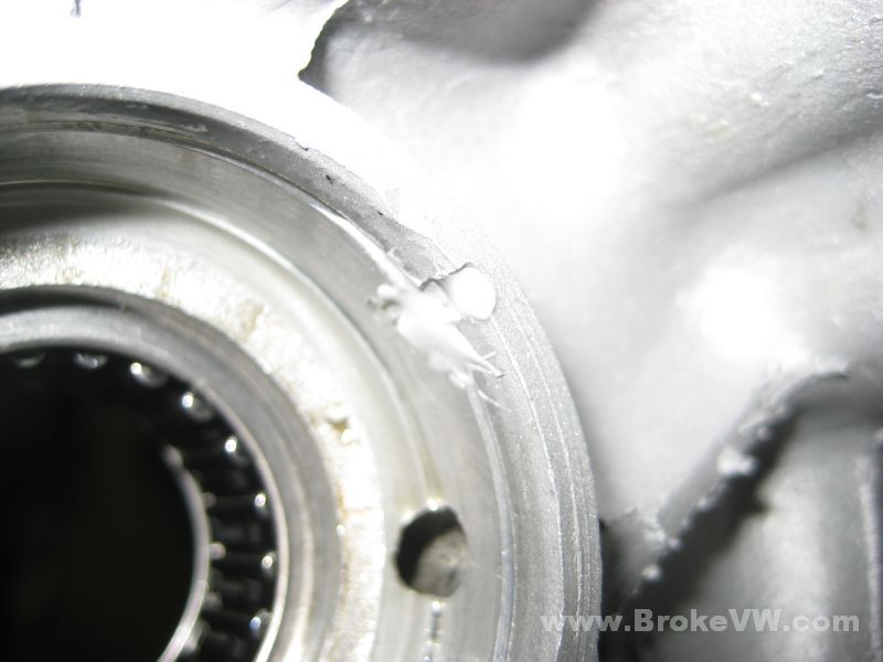
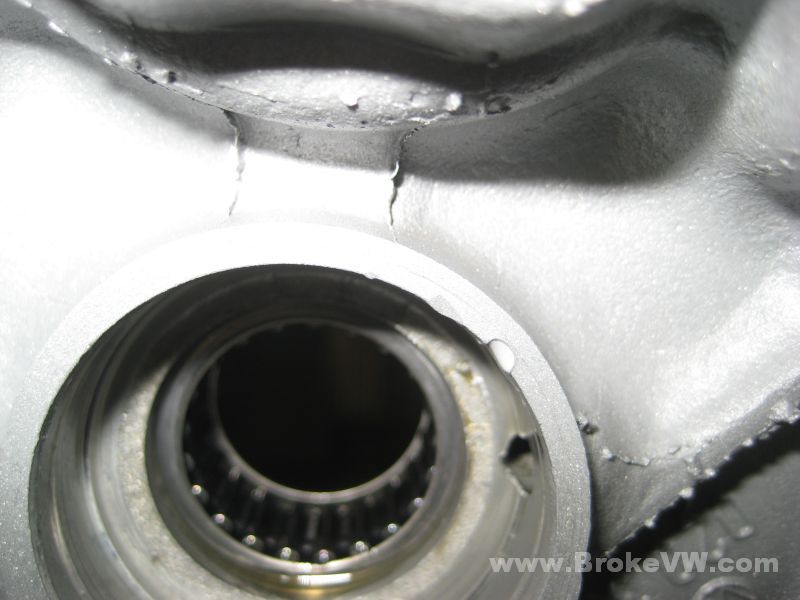
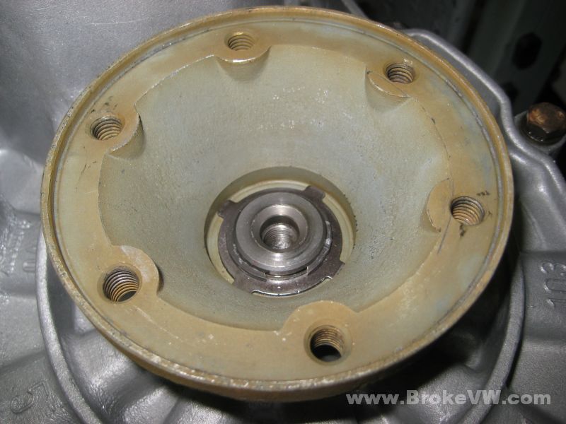
Here you can see the oil feed hole and the damage from prying an old seal out...
As discussed, we were trying to save parts costs, and make for a speedy turn around time for the repair, thus the reason for wanting to keep the seals and bearing races in place, but after a closer look at the bearings (after hitting them with brake cleaner, as opposed to just wiping them with a towel), and talking to you, those are getting replaced. With those being replaced, trying to save the flange seals would be impossible, they're easily damaged during removal, and they have to be removed to do the bearing races.
Anyway, since the seals were coming out with the tapered bearing races, and because folks were watching and reading this page and were concerned about the cleaning procedure, I just decided to clean it the usual way, so I popped those bearings out, removed those seals, and cleaned the case.
I know we discussed it, and you opted to not have it done, but I figured since it was close enough, and when they look clean people are more impressed, I just went ahead and did it anyway, so no extra charge for it, consider it a 'return customer thank you' or something.
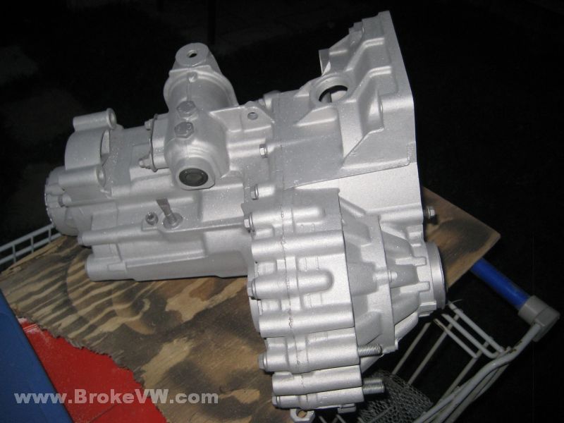
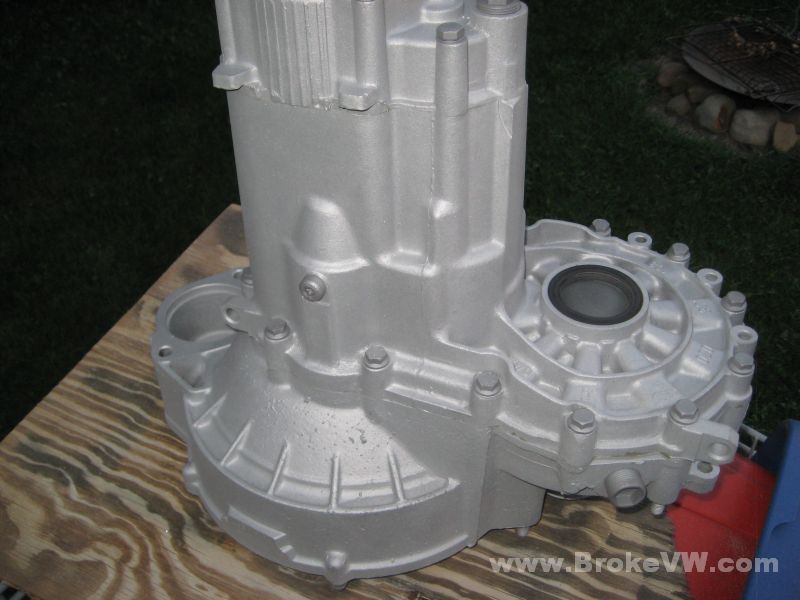
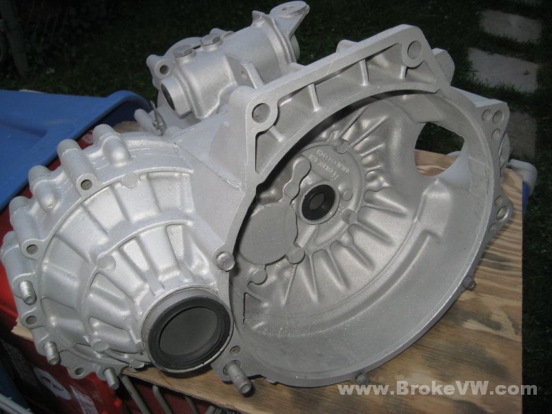
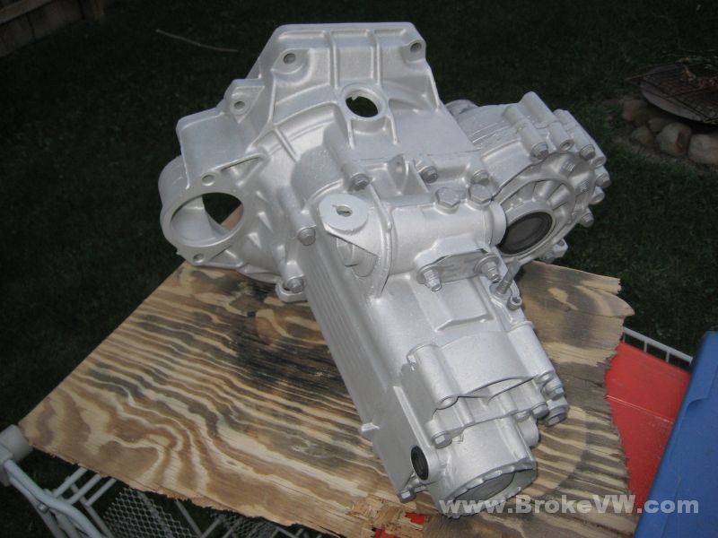
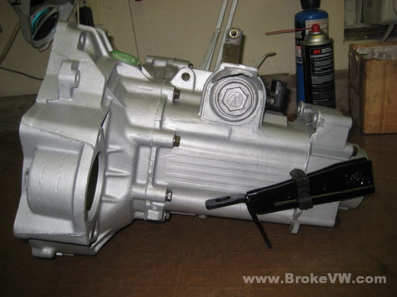
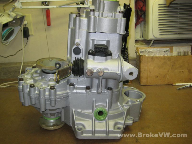
Sealed up and bolted, the internal bolt holes (clamping plate, reverse brackets) are bolted and sealed, the seal/shaft holes are plugged with rubber discs, and old seals installed to hold them in place, and seal the hole up. The speedo has a plug in it (an old speedo shoved in from the inside out), an old green end cap is installed, bolts in the holes in the bellhousing to keep them sealed, and this is the "before" shot...
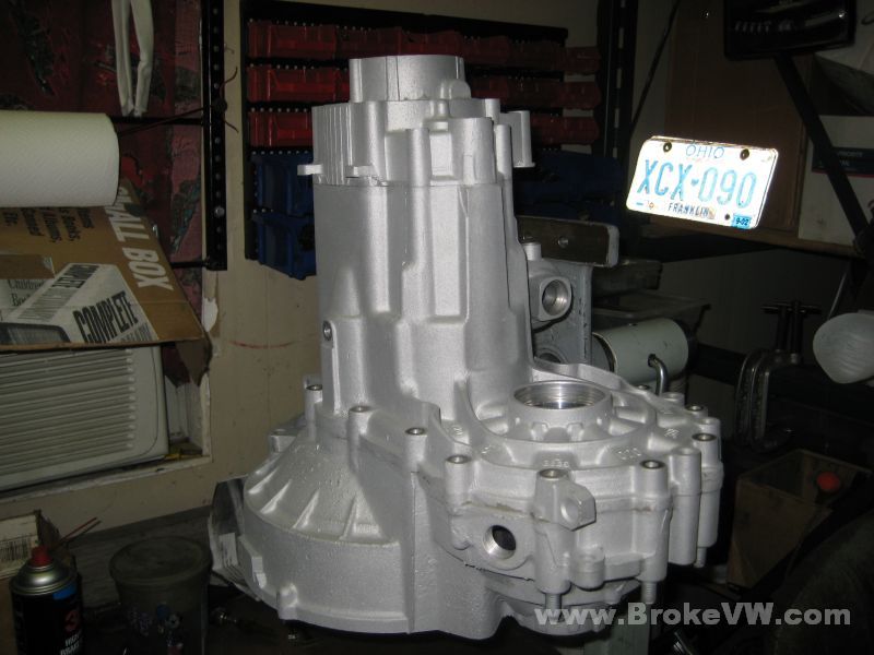
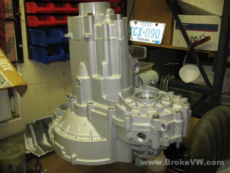
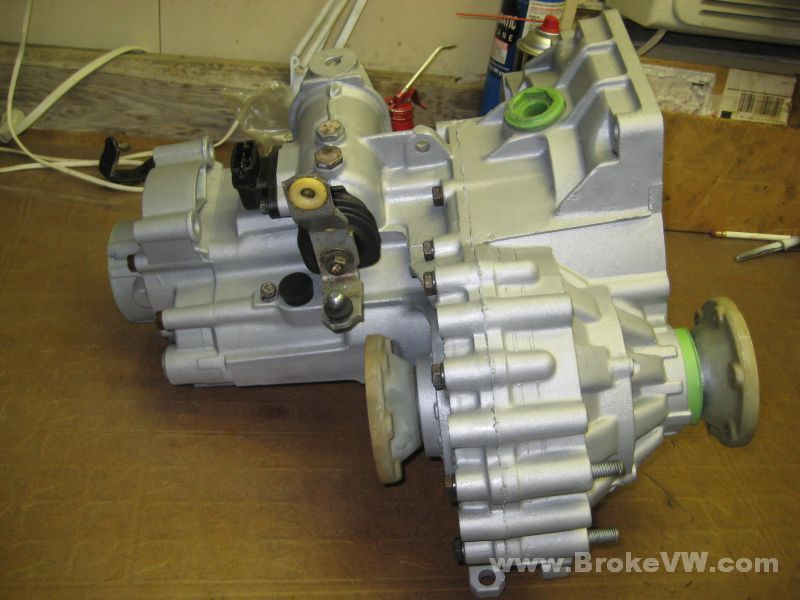
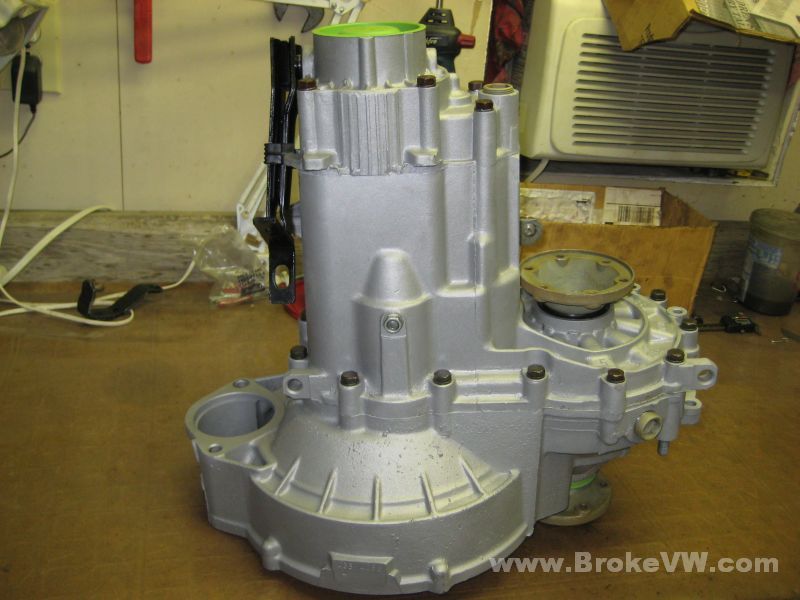
And the "after" shot...
That case was pretty corroded, I didn't spend a lot of time on it, just hitting what was easily removed, but much of the old stain came off. There are still spots on it, dark spots, that's the corrosion that is deep into the case, so it didn't come out, but for the most part, it cleaned up OK enough.
It was blasted with medium sand, then I went over it again with #80 glass bead to remove the sparkling finish that the sand blasting leaves. The sand leaves many flat facets on the case, they catch the light and glitter. To remove those, the round glass bead is used, it causes it to get "soft" looking, as it rounds all those facets out, and it smooths the finish, and makes it look nicer than the raw blasted aluminum.
I've got to get it split apart, then rinse it a few times and get it dried out, then I'll start building the assemblies inside (5th set, input shaft, the LSD, shift forks, etc.) and will get started on setting the preloads for the LSD and output shaft bearings. Once those are adjusted, I can get the trans built and sent back, hopefully with plenty of time for your next event.
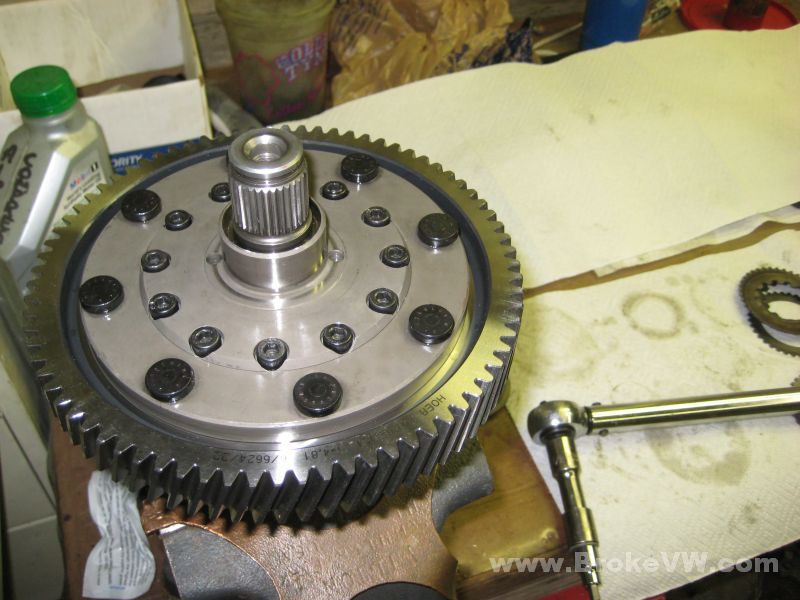
More pics... here is the diff cage cleaned out and ready to be assembled. I went ahead and assembled it up to the point of installing the bolts, I'm waiting to hear from the UK to make sure everything is right.
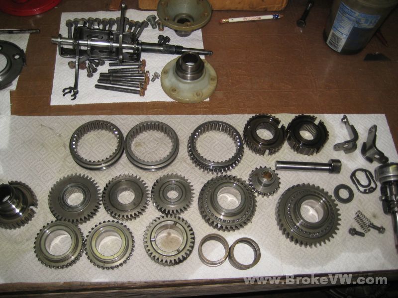
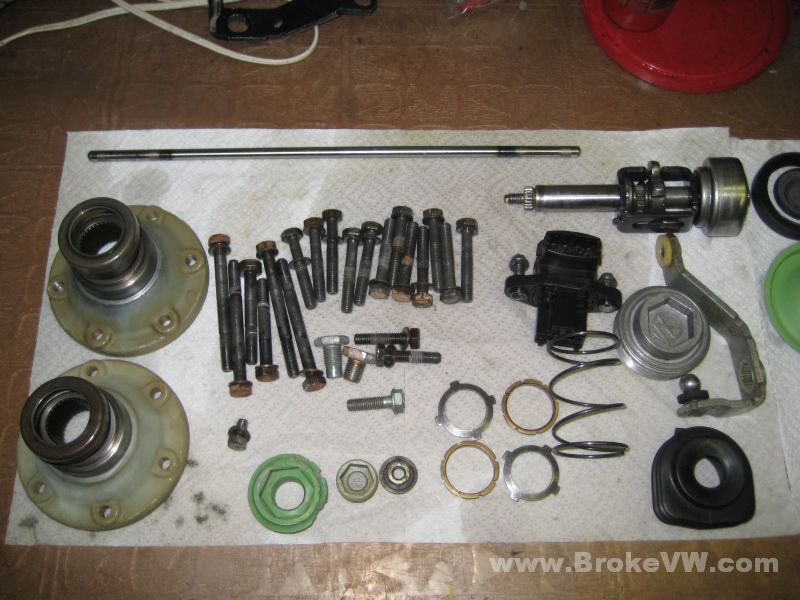
Cleaned and oiled parts waiting to be built and installed...
More parts, and the flanges I'm replacing your damaged flange with, they're zinc plated and yellow chromate dipped...
When they're not being worked on, the parts get covered to prevent dust from settling on them. They get wiped off before being used, but the more debris I can prevent, the better...
Pics of the old clutch discs and the damaged flange...
Update 6/26/09
I have the LSD adjusted, the preload is between 140-150 ft-lbs. on each side, and you had asked for something between 130-150, so I think this will do it.
I made the shims from the diff bearing shims, I had to open them up to a larger ID, but they did the trick. I made a 1.0mm and a 0.6mm and a 0.15mm shim, the 0.6mm was used, the 1.0mm I'll send back with the unused clutch discs, and the 0.15mm isn't worth hanging onto, so I tossed it.
Here is a pic of the shim...
It has to be able to fit around the thrust washer and the wavy washer... and the OD is just about perfect for contacting just that flat portion of the bellville washer and nothing else, so that was handy...
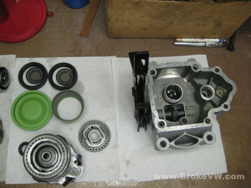
Here is the 1.0mm shim, and a pic of the top cover with and without the shim in place, I put it on the top cover so you can see where it sits once installed...
The bolts cleaned and ready for Loctite...

Did you notice there were only 11 bolts? I didn't either, until I had an empty hole... #12 rolled under the edge of another towel, but I found it:)
When assembling the diff, I think the strange figures I got for the L:R side before may have been due to the parts not seating. Specifically, I think it might be the thrust washer or wavy washer that might be acting up. In the process of trying to get the preload adjusted, I've had this thing apart quite a few times.
I've found that when putting the top cover on, if you snug the bolts to the cover, but not tighten them (just enough to make the parts contact each other), then grab the ring gear (with one output shaft in the vise) and spin it both directions, it will be tight at first, then suddenly get loose. I think those are the washers seating where they should be. If you just tighten the top cover bolts without spinning the LSD around, it could pinch those parts out of alignment, which would be the same as adding a gob of preload... and if it was screwed up on just one side, that could affect that side and not the other, so that might have been it.
The last several times I put it back together, I would spin it to seat everything, and the torque measurements started becoming more consistent and started making more sense, so if you ever have it apart in the future, when putting it back together, leave it loose, spin it around each way, then tighten the bolts to 16 ft-lbs.
Update 6/30/09
I've got the new cryo treated bearings installed onto the output shaft and the new race pressed into the bearing plate...
The input shaft is built with 3rd and 4th installed, and the LSD has new bearings installed, also cryo treated...
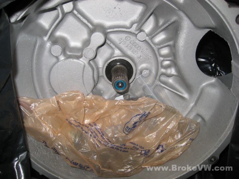
The 5th gear assembly is built and ready to install, and there is a new bushing and seal installed into the end of the input shaft...
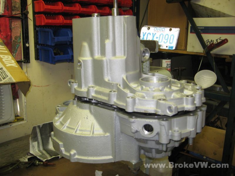
The case is rinsed and dried and mounted onto the rotisserie...
Everything is cleaned and ready to be built...
To keep the case clean while building the trans, the case is sprayed with WD-40. This keeps fingerprints and smudges trapped in the oil, and to clean it when it is done, you just wipe it with a paper towel wet with WD-40, and it removes any grease or oil on the case. The WD-40 eventually evaporates away in a week or so, or it can be rinsed off with brake cleaner....
The case fully wet with the WD, and ready to be assembled...
I'll get started with the bearing preloads for the LSD and the output shaft next, and start getting things put back together.
7/02/09
More pics of the build...
The 5th housing assembled, the arm is just painted with some rattle-can paint, not zinc plated, so it isn't as durable, but it looks better than when it arrived, and it might even last a few weeks before starting to rust again...
Pressing in the input shaft ball bearing, the output shaft roller bearing, and the LSD bearing race...
The bearings and race pressed into place, I used a 0.60mm and a 0.15mm shim behind the LSD race...
A pic of the new bearing surface...
The output shaft bearing preload is about 6 in-lbs., and spec is 4.4 to 13.3, a 0.85mm shim was used...
The LSD bearing preload spec is 11-31 in-lbs., yours are adjusted to 31, so at the top of the range, but still in spec...
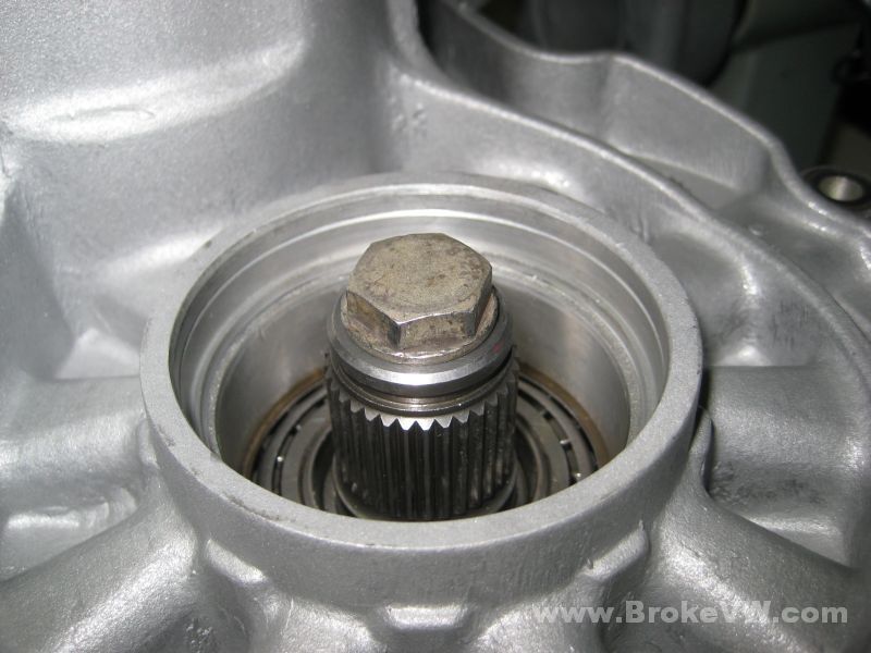
Your LSD doesn't use a M10-x1.50 thread pitch, so I had to use a M10x1.0 bolt to measure the preload....
The reverse relay brackets being installed...
The output shaft bearing plate being torqued down...
The input shaft seal, oiled and greased, and ready to be installed. It is easier to install without the input shaft in the way...
I used some VW trans sealant to try to fill the gouge in the case, and I think it will be OK...
The support bar bolted in place...
The input shaft thrust washer, 1st gear needle bearing, and 1st gear installed...
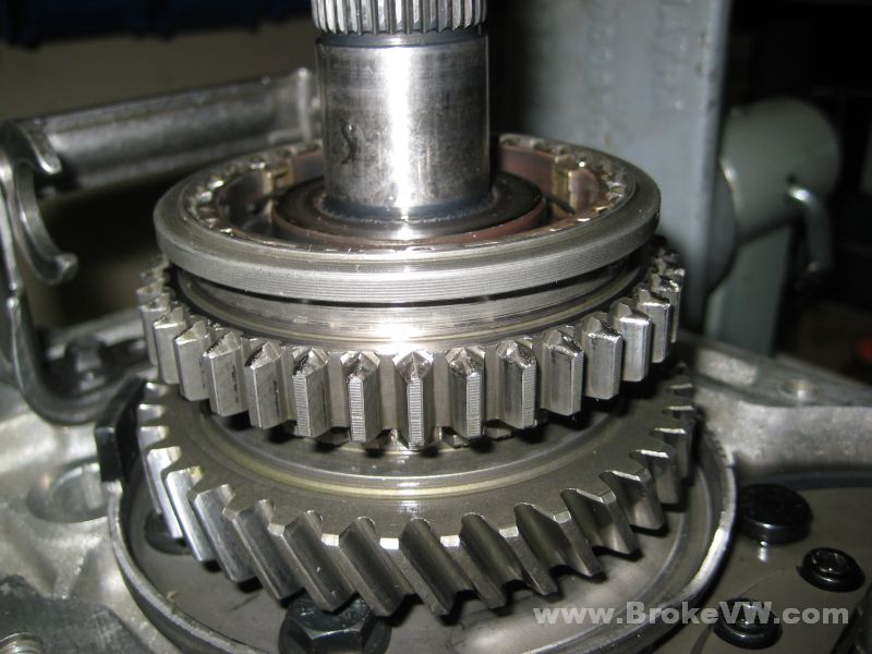
Heating the 1st/2nd sync hub to 212F and dropping it on, the press is just to be sure it seats fully...
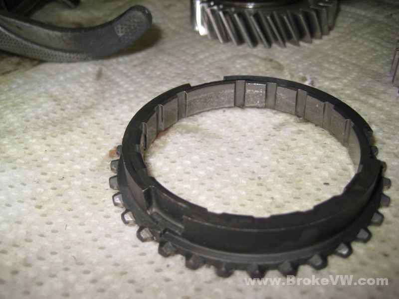
A pic of the 2nd gear sync ring... I took the pic for someone else who never had seen this style of ring before...
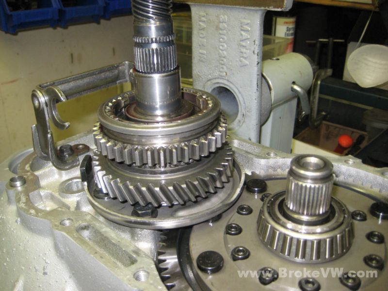
The sync hub assembled, ready to have 2nd gear needle bearing race installed...
The race was a little loose, heating it and letting it cool in spot usually does the trick, but for your race, I put a drop of loctite on it to hold it tight on the shaft, heating it wouldn't allow it to cool and contract enough to get tight...
The 3rd gear circlip is a 2.8mm, it snapped in fully and hopefully won't pop out...
New 4th gear 2.5mm circlips for 4th gear...
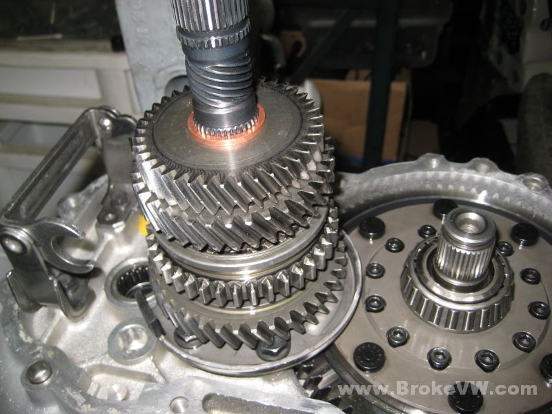
Using the support bar, the input shaft is supported from below, and also held in the correct spot, slightly lifted by the bar so the gears are aligned inside...
The input shaft installed with the completed output shaft...
Reverse gear, the magnet, and the shift forks installed...
The remaining parts...
The case just sat on top while I take a break (it also gets covered with clean towels, along with the parts)...
I'm going to work late tonight, and try to get it built, so it can ship out tomorrow. I've got to clean the mating surfaces with brake cleaner, get sealant on them, press the case together, install 5th, bolt on the 5th housing, install the selector and seal, install the flange seals and press the flanges on, then spin everything over and run it through the gears to make sure it feels right, then it should be ready to be torn up again!
More pics...
The case sealed and bolted up with 5th gears installed...
Here is an out of focus pic showing the threads on the drain plug hole... they have seen better days. They should work, but they're rough, and are about worn out...
The selector installed, it is easier to install the seal with the shaft in place...
The 5th gear fork lock installed...
The reverse switch and selector detents installed with the new seal....
The flange seal installed with the bronze conical ring...
The flange installed....
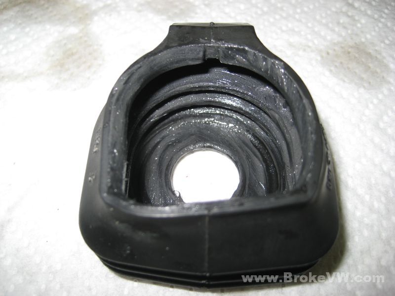
The inside of the selector boot coated with grease...
The last part... the green VW end cap...
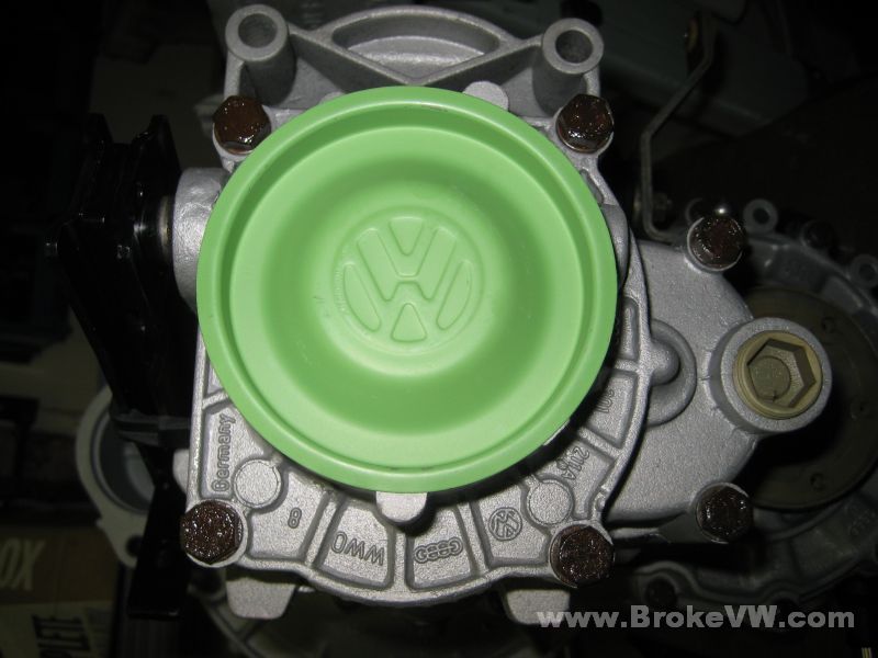
All done...
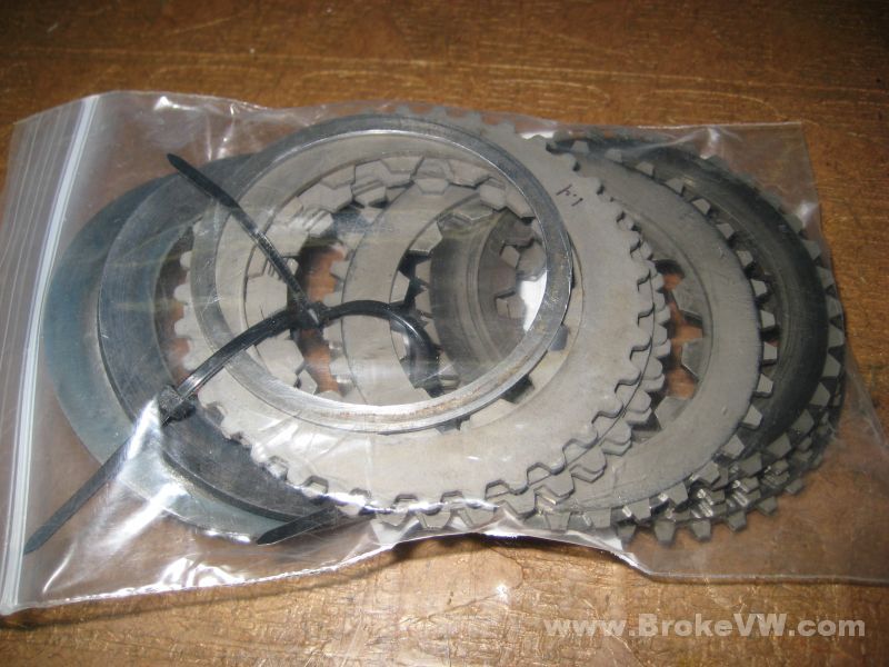
The old clutch discs, the 6 new ones, the 2 old bellville washers, and the 1mm shim I made for the LSD...
The old speedo cable (it's shot, it needs replaced, and the gear soon as well!) is in the bag, the clutch discs behind it, all in the bellhousing...
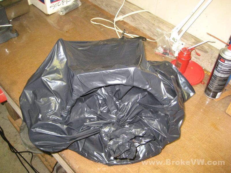
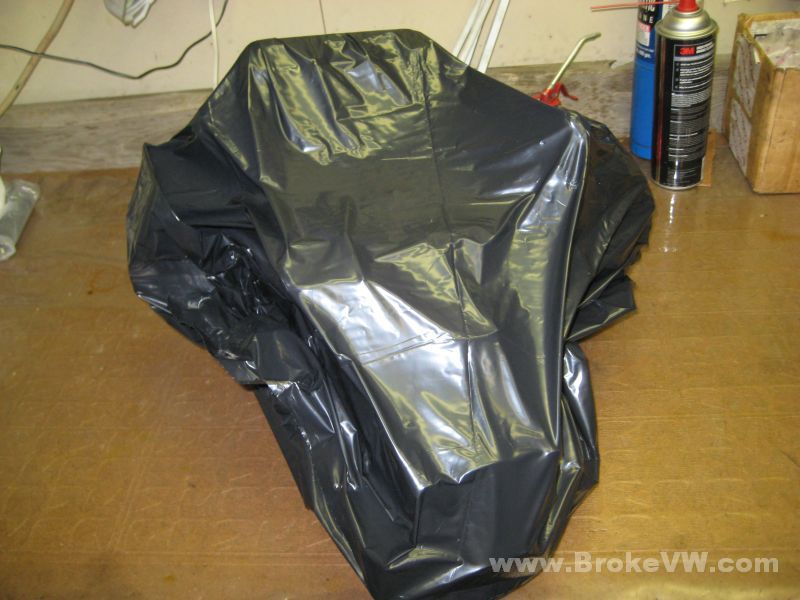
One large contractor bag and a small shop vac later, and the trans is bagged up...
I'll ship it out tomorrow, let me know if you have any questions, or problems with it, thanks!
Update 7/27/09
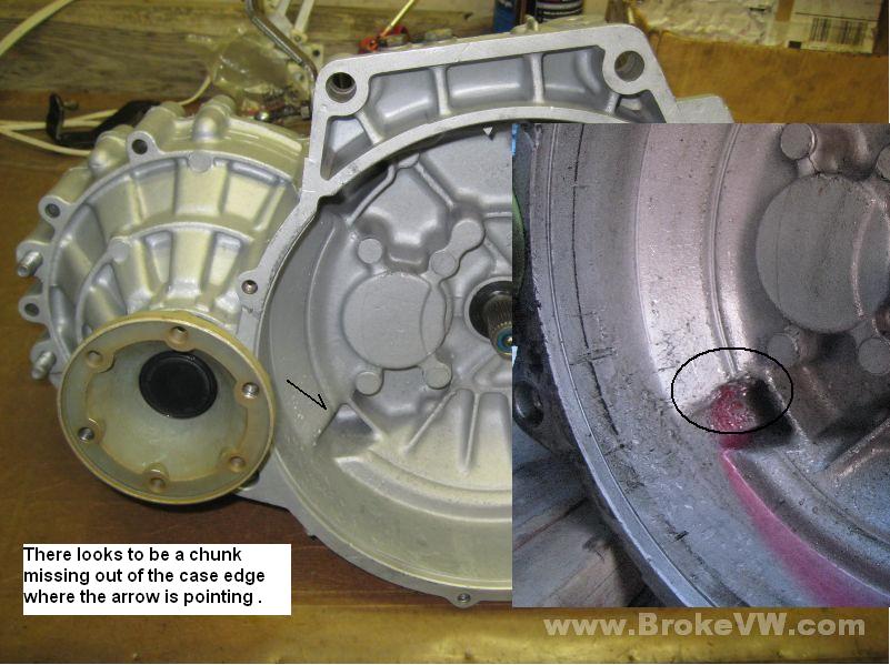
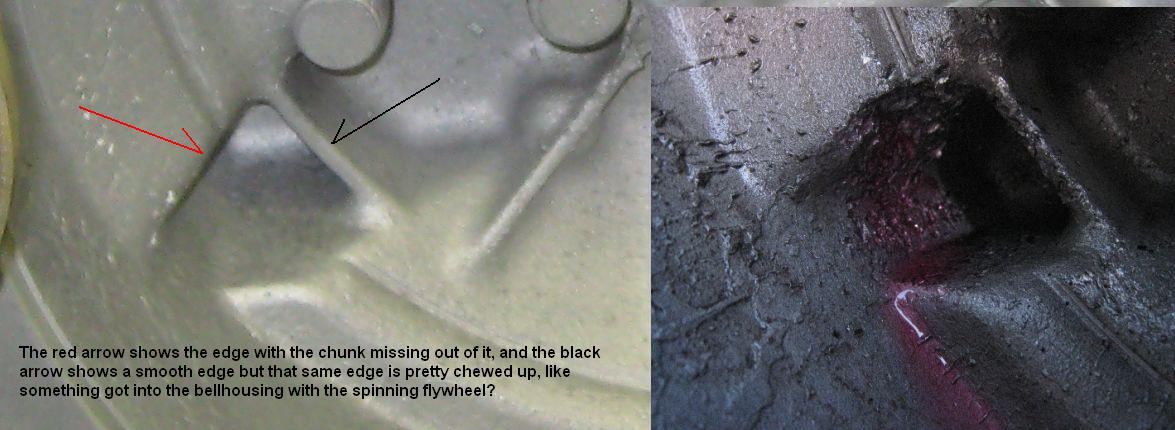
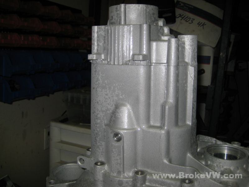
Well, I've looked the pics over closely and compared them to a pic I took before it left here (8 pics or so above), and made these, it shows what looks to be a chunk missing out of the case, and it would seem the damage came from the outside, like a clutch exploded or something foreign was spinning around in with the flywheel.... do you use that thin sheet metal shield between the engine and the trans that covers the bottom of the bellhousing? Could it be possible something like gravel got tossed into the bellhousing and caused the damage?
Here are the pics..